4.3.3. Input Files
4.3.3.1. Important changes introduced in v4.0
Some important changes have been introduced starting from version 4.0. Please refer to AeroDyn changes starting from v4.x to understand the link between the old and new inputs.
The documentation below has been updated to incorporate these changes.
4.3.3.2. Introduction
The user configures the aerodynamic model parameters via a primary AeroDyn input file, as well as separate input files for airfoil and blade data. When used in standalone mode, an additional driver input file is required. The AeroDyn driver and driver input file are detailed in Section 4.3.6. The driver file specifies initialization inputs normally provided to AeroDyn by OpenFAST, as well as the per-time-step inputs to AeroDyn.
As an example, the driver.dvr file is the main driver, the input.dat is
the primary input file, the blade.dat file contains the blade geometry data,
and the airfoil.dat file contains the airfoil angle of attack, lift, drag,
moment coefficients, and pressure coefficients. Example input files are
included in Section 4.3.11.
No lines should be added or removed from the input files, except in tables where the number of rows is specified and comment lines in the AeroDyn airfoil data files.
4.3.3.2.1. Units
AeroDyn uses the SI system (kg, m, s, N). Angles are assumed to be in radians unless otherwise specified.
4.3.3.2.2. AeroDyn Primary Input File
The primary AeroDyn input file defines modeling options, environmental conditions (except freestream flow), airfoils, tower nodal discretization and properties, tower, hub, and nacelle properties, as well as output file specifications.
The file is organized into several functional sections. Each section corresponds to an aspect of the aerodynamics model. A sample AeroDyn primary input file is given in Section 4.3.11.
The input file begins with two lines of header information which is for your use, but is not used by the software.
4.3.3.3. General Options
Set the Echo flag to TRUE if you wish to have AeroDyn echo the
contents of the AeroDyn primary, airfoil, and blade input files (useful
for debugging errors in the input files). The echo file has the naming
convention of OutRootFile.AD.ech. OutRootFile is either
specified in the I/O SETTINGS section of the driver input file when
running AeroDyn standalone, or by the OpenFAST program when running a
coupled simulation.
DTAero sets the time step for the aerodynamic calculations. For
accuracy and numerical stability, we recommend that DTAero be set
such that there are at least 200 azimuth steps per rotor revolution.
However, when AeroDyn is coupled to OpenFAST, OpenFAST may require time steps
much smaller than this rule of thumb. If UA is enabled while using very
small time steps, you may need to recompile AeroDyn in double precision
to avoid numerical problems in the UA routines. The keyword DEFAULT
for DTAero may be used to indicate that AeroDyn should employ the
time step prescribed by the driver code (OpenFAST or the standalone driver
program).
Wake_Mod
Set Wake_Mod to 0 if you want to have zero induced velocities.
Set it to 1 to include these effects using the BEM theory model.
When Wake_Mod is set to 3, the free vortex wake model is used, also referred to as OLAF (see
Section 4.4). Wake_Mod cannot be set to 3 during linearization analyses.
Note
Link to old inputs: The previous input WakeMod is removed, WakeMod=2 used to mean DBEMT, but this now controlled using DBEMT_Mod. Wake_Mod=2 is a placeholder for future induction calculation method.
~~AFAeroMod~~
This input has been removed. See UA_Mod below.
~~FrozenWake~~
This input has been removed. See DBEMT_Mod below.
Set TwrPotent to 0 to disable the
potential-flow influence of the tower on the fluid flow local to the
blade, 1 to enable the standard potential-flow model, or 2 to include
the Bak correction in the potential-flow model.
Set the TwrShadow to 0 to disable to the tower shadow model,
1 to enable the Powles tower shadow model, or 2 to use the Eames tower
shadow model. These models calculate the influence of the tower on the
flow local to the blade based on the downstream tower shadow model. If
the tower influence from potential flow and tower shadow are both
enabled, the two influences will be superimposed.
Set the TwrAero flag to TRUE to calculate fluid drag loads on the
tower or FALSE to disable these effects.
During linearization analyses
with AeroDyn coupled OpenFAST and BEM enabled (Wake_Mod = 1), set the
DBEMT_Mod=-1 to employ frozen-wake assumptions
(i.e. to fix the axial and tangential induces velocities, and, at their operating-point values during linearization)
or
DBEMT_Mod=3 to use the continuous dynamic wake model.
Set the CavitCheck flag to TRUE to perform a cavitation check for MHK
turbines or FALSE to disable this calculation. If CavitCheck is
TRUE, UA_Mod must be set to 0 because the cavitation check does
not function with unsteady airfoil aerodynamics. If CavitCheck is
TRUE, the MHK flag in the AeroDyn or OpenFAST driver input file must be set
to 1 or 2 to indicate an MHK turbine is being modeled.
Set the NacelleDrag flag to TRUE to calculate the drag loads on the nacelle
or FALSE to disable this calculation.
Set the CompAA flag to TRUE to run aero-acoustic calculations. This
option is only available for Wake_Mod = 1 and is not available for
an MHK turbine. See section Section 4.5 for information on how to
use this feature.
The AA_InputFile is used to specify the input file for the aeroacoustics
sub-module. See Section 4.5 for information on how to use this
feature.
4.3.3.4. Environmental Conditions
Environmental conditions are now specified in driver input files but are left in
the AeroDyn primary input file for legacy compatibility. Use the keyword
DEFAULT to pass in values specified by the driver input file. Otherwise,
values given in the AeroDyn primary input file will overwrite those given in the
driver input file. AirDens specifies the fluid density and must be a value
greater than zero; a typical value is around 1.225 kg/m3 for air (wind
turbines) and 1025 kg/m3 for seawater (MHK turbines).
KinVisc specifies the kinematic viscosity of the fluid (used in the
Reynolds number calculation); a typical value is around 1.460E-5
m2/s for air (wind turbines) and 1.004E-6 m2/s for
seawater (MHK turbines). SpdSound is the speed of sound in the fluid
(used to calculate the Mach number within the unsteady airfoil
aerodynamics calculations); a typical value is around 340.3 m/s for air (wind
turbines) and 1500 m/s for seawater (MHK turbines). The
last two parameters in this section are only used when
CavitCheck = TRUE for MHK turbines. Patm is the atmospheric
pressure above the free surface; typically around 101,325 Pa. Pvap
is the vapor pressure of the fluid; for seawater this is typically
around 2,000 Pa.
4.3.3.5. Blade-Element/Momentum Theory Options
BEM_Mod Determines the kind of BEM algorithm to use.
BEM_Mod=2(recommended) uses the new AeroDyn BEM implementation using the local staggered polar grid coordinate system, which is more suitable for large coning. It also includes an optional momentum correction that is important for large skew (seeSkewMomCorr). The feature will be documented at a later time.BEM_Mod=1(for backward compatibility) uses the old AeroDyn BEM implementation using the NoSweepPitchTwist coordinate system.
Note
Link to old inputs: previous implementation would have BEM_Mod=1 implied.
Warning
BEM_Mod currently governs the coordinate system used for “ill-defined” outputs (outputs that don’t have a specified coordinate system) such as the ones that ends with “x” and “y”. Other ill-defined outputs are the typical BEM quantities such as “AxInd”, “TnInd”, “Phi”, etc. These are defined in a different coordinate system depending on BEM_Mod. For consistency across differents Wake_Mod (even when Wake_Mod/=1), we use BEM_Mod to determine the coordinate system of the ill-defined outputs.
The following inputs in this section are only used when Wake_Mod = 1.
Skew_Mod
Skew_Mod determines the skew correction model (for yaw and tilt):
Skew_Mod=1: activates Glauert’s skew model (recommended). This model has two components: a momentum correction (SkewMomCorr` `), and a velocity redistribution model (``SkewRedistr_Mod).Skew_Mod=0means no skew model at all (not recommended)Skew_Mod=-1throws away non-normal component (for linearization). This setting makes sure the wind speed is always normal to the rotor to limit periodic variation of the wind speed if the rotor is not perpendicular to the wind (e.g. tower top tilting or tilt). This is mostly needed for linearization.
Currently (Skew_Mod=0) or (Skew_Mod=1 and SkewModCorr=False and SkewRedistr_Mod = 0) are the same, both set of inputs turn off the skew correction entirely.
Note
Link to old inputs: Previous implementations always had the skew model on. Skew_Mod=-1 replaces the old SkewMod=0 (an option that few users were using).
SkewMomCorr
Turns the skew momentum correction on or off [used only when Skew_Mod=1]
The feature will be documented at a later time.
Note
Link to old inputs: the previous behavior would be SkewMomCorr=False
SkewRedistr_Mod
SkewRedistr_Mod allows to turn on and off the induced velocity redistribution model, and give room for other models to be selected/implemented. Default=1.
0: no redistribution
1: Glauert (Pitt-Peters) redistribution model
SkewRedistrFactor
Defines the constant used in the Glauert redistribution model (SkewRedistr_Mod=1).
Use "default" to use the default value of \(\frac{15 \pi}{32}\).
4.3.3.6. BEM Algorithm options
Set TipLoss to TRUE to include the Prandtl tip-loss model or FALSE
to disable it. Likewise, set HubLoss to TRUE to include the
Prandtl hub-loss model or FALSE to disable it.
Set TanInd to TRUE to include tangential induction (from the
angular momentum balance) in the BEM solution or FALSE to neglect it.
Set AIDrag to TRUE to include drag in the axial-induction
calculation or FALSE to neglect it. If TanInd = TRUE, set
TIDrag to TRUE to include drag in the tangential-induction
calculation or FALSE to neglect it. Even when drag is not used in the
BEM iteration, drag is still used to calculate the nodal loads once the
induction has been found,
IndToler sets the convergence threshold for the iterative
nonlinear solve of the BEM solution. The nonlinear solve is in terms of
the inflow angle, but IndToler represents the tolerance of the
nondimensional residual equation, with no physical association possible.
When the keyword DEFAULT is used in place of a numerical value,
IndToler will be set to 5E-5 when AeroDyn is compiled in single
precision and to 5E-10 when AeroDyn is compiled in double precision; we
recommend using these defaults. MaxIter determines the maximum
number of iterations steps in the BEM solve. If the residual value of
the BEM solve is not less than or equal to IndToler in
MaxIter, AeroDyn will exit the BEM solver and return an error
message.
4.3.3.7. Shear corrections
The BEM algorithm may need to be corrected to account for shear. Currently, a sector average correction is implemented, as a beta feature, to limit fluctuations associated with variations of wind speed as the blade rotates.
The feature will be documented at a later time and is still at an experimental stage.
SectAvg Use Sector Averaging (flag).
The method uses sectors expanding forward and backward relative to the current azimuth of the blade (see SectAvgPsiBwd and SectAvgPsiFwd).
The velocity is averaged within this sector by attributing different weighting at different points in the sector (see SectAvgWeighting).
SectAvgWeighting Weighting function for sector average.
1=Uniform (switch) [used only when SectAvg=True]. Default is 1.
SectAvgNPoints Number of points per sectors (-) [used only when SectAvg=True]. Default is 5.
SectAvgPsiBwd Backward azimuth (in degrees) relative to the blade azimuth where the sector starts. Must be negative. [used only when SectAvg=True]. Default is -60 deg.
SectAvgPsiFwd Forward azimuth (in degrees) relative to the blade azimuth where the sector ends. Must be positive. [used only when SectAvg=True]. Default is 60 deg.
4.3.3.8. Dynamic Wake / Dynamic inflow model
The input parameters in this section are used only when Wake_Mod = 1.
The theory is described in Section 4.3.7.2.
The dynamic wake (also called dynamic inflow) model is governed by the input DBEMT_Mod:
0: no dynamic wake, also called quasi-steady wake model (not recommended).-1: frozen wake, the induced velocities at a given operating point will remain constant (useful for simplified linearization only).1: discrete-time Oye’s model, with constant \(\tau_1\)2: discrete-time Oye’s model, with varying \(\tau_1\), automatically adjusted based on inflow. (recommended for time-domain simulations)3: continuous-time Oye’s model, with constant \(\tau_1\) (recommended for linearization)
For DBEMT_Mod=1 or DBEMT_Mod=3 it is the user responsability to set the value of \(\tau_1\) (i.e. tau1_const) according to the expression given in Section 4.3.7.2, using an estimate of what the mean axial induction (\(\overline{a}\)) and the mean relative wind velocity across the rotor (\(\overline{U_0}\)) are for a given simulation.
Only the options DBEMT_Mod={-1,3} can be used for linearization.
Note
Link to old inputs: The option DBEMT_Mod=-1 has the same behavior as the old FrozenWake=True. DBEMT_Mod=0 has the same behavior as the previous WakeMod=1 option. DBEMT_Mod=J (J in 1,2,3) , has the same behavior as the previous WakeMod=2 & DBEMT_Mod=J
4.3.3.9. OLAF – cOnvecting LAgrangian Filaments (Free Vortex Wake) Theory Options
The input parameters in this section are used only when Wake_Mod = 3.
The settings for the free vortex wake model are set in the OLAF input file
described in Section 4.4.4. OLAFInputFileName is the filename
for this input file.
4.3.3.10. Unsteady Airfoil Aerodynamics Options
AoA34
Determine whether the baseline angle of attack is sampled at the 3/4 chord or at the aerodynamic center point.
Most UA_Mod will require AoA34 to be set to true. But when using quasi-steady aerodynamics, the user may want to set it to true or false.
Warning
This feature is currently not implemented due to a lag between the dev and dev-unstable branch.
Note
Link to previous inputs: AFAeroMod=1 implies AoA34=False. But to have a fair comparison between steady and unsteady aerodynamics model, it would be best to set AoA34=True when doing quasi-steady aero.
UA_Mod determines the UA model. It has the following options:
0: no unsteady arifoil aerodynamics,1: the discrete-time model of Beddoes-Leishman (B-L) (not currently functional),2: the extensions to B-L developed by González (changes in Cn, Cc, Cm)3: the extensions to B-L developed by Minnema/Pierce (changes in Cc and Cm)4: 4-states continuous-time B-L model developed by Hansen, Gaunna, and Madsen (HGM). NOTE: might require smaller time steps until a stiff integrator is implemented.5: 5-states continuous-time B-L model similar to HGM with an additional state for vortex generation6: 1-state continuous-time developed by Oye7: discrete-time Boeing-Vertol (BV) model
Linearization is supported with UA_Mod=4,5,6 (which use continuous-time states) but not with the other models. The different models are described in Section 4.3.8.
Note
Link to old inputs: If UA_Mod>0, then this is equivalent to the old AFAeroMod=2.
While all of the UA models are documented in this manual, the original B-L model is not yet functional. Testing has shown that the González and Minnema/Pierce models produce reasonable hysteresis of the normal force, tangential force, and pitching-moment coefficients if the UA model parameters are set appropriately for a given airfoil, Reynolds number, and/or Mach number. However, the results will differ a bit from earlier versions of AeroDyn, (which was based on the Minnema/Pierce extensions to B-L) even if the default UA model parameters are used, due to differences in the UA model logic between the versions. We recommend that users run test cases with uniform inflow and fixed yaw error (e.g., through the standalone AeroDyn driver) to examine the accuracy of the normal force, tangential force, and pitching-moment coefficient hysteresis and to adjust the UA model parameters appropriately.
FLookup determines how the nondimensional separation distance
value, f’, will be calculated. When FLookup is set to TRUE, f’
is determined via a lookup into the static lift-force coefficient and
drag-force coefficient data. Using best-fit exponential equations
(``FLookup = FALSE``) is not yet available, so ``FLookup`` must be
``TRUE`` in this version of AeroDyn. Note, FLookup is not used
when UA_Mod=4 or UA_Mod=5.
UAStartRad is the starting rotor radius where dynamic stall
will be turned on. Enter a number between 0 and 1, representing a fraction of rotor radius,
to indicate where unsteady aerodynamics should begin turning on. If this line is
omitted from the input file, UAStartRad will default to 0 (turning on at the blade root).
All blade nodes that are located at a rotor radius less than UAStartRad will have
unsteady aerodynamics turned off for the entire simulation.
UAEndRad is the ending rotor radius where dynamic stall
will be turned on. Enter a number between 0 and 1, representing a fraction of rotor radius,
to indicate the last rotor radius where unsteady aerodynamics should be turned on. If this line is
omitted from the input file, UAEndRad will default to 1 (the blade tip).
All blade nodes that are located at a rotor radius greater than UAEndRad will have
unsteady aerodynamics turned off for the entire simulation.
4.3.3.11. Airfoil Information
This section defines the airfoil data input file information. The airfoil data input files themselves (one for each airfoil) include tables containing coefficients of lift force, drag force, and optionally pitching moment, and minimum pressure versus AoA, as well as UA model parameters, and are described in Section 4.3.3.19.1.
The first 5 lines in the AIRFOIL INFORMATION section relate to the
format of the tables of static airfoil coefficients within each of the
airfoil input files. InCol_Alfa, InCol_Cl,
InCol_Cd, InCol_Cm, and InCol_Cpmin are column
numbers in the tables containing the AoA, lift-force coefficient,
drag-force coefficient, pitching-moment coefficient, and minimum
pressure coefficient, respectively (normally these are 1, 2, 3, 4, and
5, respectively). If pitching-moment terms are neglected with
UseBlCm = FALSE, InCol_Cm may be set to zero, and if the
cavitation check is disabled with CavitCheck = FALSE,
InCol_Cpmin may be set to zero.
Specify the number of airfoil data input files to be used using
NumAFfiles, followed by NumAFfiles lines of filenames. The
file names should be in quotations and can contain an absolute path or a
relative path e.g., “C:\airfoils\S809_CLN_298.dat” or
“airfoils\S809_CLN_298.dat”. If you use relative paths, it is
relative to the location of the file in which it is specified. The blade
data input files will reference these airfoil data using their line
identifier, where the first airfoil file is numbered 1 and the last
airfoil file is numbered NumAFfiles.
4.3.3.12. Rotor/Blade Properties
Set UseBlCm to TRUE to include pitching-moment terms in the blade
airfoil aerodynamics or FALSE to neglect them; if UseBlCm = TRUE,
pitching-moment coefficient data must be included in the airfoil data
tables with InCol_Cm not equal to zero.
The blade nodal discretization, geometry, twist, chord, airfoil
identifier, and buoyancy/added mass/fluid inertia properties are set in separate input files for each
blade, described in Section 4.3.3.19.2. ADBlFile(1) is the
filename for blade 1, ADBlFile(2) is the filename for blade 2, and
ADBlFile(3) is the filename for blade 3, respectively; the latter is not
used for two-bladed rotors and the latter two are not used for one-bladed
rotors. The file names should be in quotations and can contain an absolute path
or a relative path. The data in each file need not be identical, which
permits modeling of aerodynamic imbalances.
4.3.3.13. Hub Properties
The input parameters in this section pertain to the calculation of buoyant loads on the hub.
VolHub is the volume of the hub and HubCenBx is the x offset of the hub
center of buoyancy from the hub center in local hub coordinates;
offsets in the y and z directions are assumed to be zero. To neglect buoyant
loads on the hub, set VolHub to 0.
Since the hub and blades are joined elements, hub buoyancy should be included if blade buoyancy is included, and vice versa.
4.3.3.14. Nacelle Properties
The input parameters in this section pertain to the calculation of buoyant and drag loads
on the nacelle and are only used when MHK > 0 or NacelleDrag = TRUE.
VolNac is the volume of the nacelle and NacCenB` is the
position (x,y,z vector) of the nacelle center of buoyancy from
the yaw bearing in local nacelle coordinates. To neglect buoyant
loads on the nacelle, set VolNac to 0. Only used when Buoyancy = TRUE.
NacArea are the projected areas (Ax,Ay,Az vector) of the nacelle in the nacelle coordinate system,
NacCd are the drag coefficients (Cdx, Cdy, Cdz vector) for the three nacelle areas defined by NacArea``and ``NacDragAC is the
position (x,y,z vector) of the nacelle aerodynamic center from
the yaw bearing in local nacelle coordinates. Only used when NacelleDrag = TRUE.
4.3.3.15. Tail fin AeroDynamics
The tail fin aerodynamics section contains two lines:
======  Tail fin AeroDynamics ========================================================================
    true       TFinAero     - Calculate tail fin aerodynamics model (flag)
  ""           TFinFile     - Input file for tail fin aerodynamics [used only when TFinAero=True]
======  Tower Influence and Aerodynamics =============================================================
TFinAero Flag to activate the tail fin aerodynamics calculation.
TFinFile Path (absolute or relative to the AeroDyn input file) where the tail fin input file is located.
The content of the tail fin input file is described in Section 4.3.3.19.3.
4.3.3.16. Tower Influence and Aerodynamics
The input parameters in this section pertain to the tower influence, tower drag,
tower buoyancy, tower added mass, and/or tower fluid inertia calculations and are only used when TwrPotent >
0, TwrShadow > 0, TwrAero = TRUE, MHK = 1, or MHK = 2.
NumTwrNds is the user-specified number of tower analysis nodes and
determines the number of rows in the subsequent table (after two table
header lines). NumTwrNds must be greater than or equal to two; the
higher the number, the finer the resolution and longer the computational
time; we recommend that NumTwrNds be between 10 and 20 to balance
accuracy with computational expense. For each node, TwrElev
specifies the local elevation of the tower node above ground (or relative
to MSL for offshore wind and floating MHK turbines or relative to the seabed for fixed MHK turbines),
TwrDiam specifies the local tower diameter, TwrCd specifies the
local tower drag-force coefficient, TwrTI specifies the
turbulence intensity used in the Eames tower shadow model
(TwrShadow = 2) as a fraction (rather than a percentage) of the
wind fluctuation, TwrCb specifies the tower buoyancy coefficient,
TwrCp specifies the tower dynamic pressure coefficient, and
TwrCa specifies the tower added mass coefficient.
TwrElev must be entered in monotonically increasing order—from the lowest
(tower-base) to the highest (tower-top) elevation. For floating MHK turbines with
the tower below MSL, tower nodes should be entered as increasingly negative values,
from the tower-base (closest to the platform) to the tower-top (closest to the nacelle).
Values of TwrTI between 0.05 and 0.4 are recommended. Values larger than 0.4 up to 1 will trigger a
warning that the results will need to be interpreted carefully, but the code
will allow such values for scientific investigation purposes. TwrCb is
defined at each node as the cross-sectional area of the tower divided by the
area of a circle with diameter equal to the characteristic length of the tower
cross section (i.e., TwrDiam). For towers with circular cross-sections,
TwrCb will likely be 1.0 at each node. To neglect buoyant loads on the
tower, set TwrCb to 0. To neglect added mass loads on the
tower, set TwrCa to 0. To neglect fluid inertia loads on the
tower, set TwrCp to 0. See Fig. 4.5.
4.3.3.17. Outputs
Specifying SumPrint to TRUE causes AeroDyn to generate a summary
file with name <OutFileRoot>.AD.sum. <OutFileRoot> is either
specified in the I/O SETTINGS section of the driver input file when
running AeroDyn standalone, or by the OpenFAST program when running a
coupled simulation. See Section 4.3.4.2 for summary file details.
If UAMod>0, the unsteady aero module will also generate a file
called <OutFileRoot>.UA.sum that will list all of the UA parameters
used in the airfoil tables. This allows the user to check what values
are being used in case the code has computed the parameters
without user input.
AeroDyn can output aerodynamic and kinematic quantities at up to nine nodes specified along the tower and up to nine nodes along each blade. For outputs at every blade node, see Section 4.3.3.18.
NBlOuts specifies the number of blade nodes that output is
requested for (0 to 9) and BlOutNd on the next line is a list
NBlOuts long of node numbers between 1 and NumBlNds
(corresponding to a row number in the blade analysis node table in the
blade data input files), separated by any combination of commas,
semicolons, spaces, and/or tabs. All blades have the same output node
numbers. NTwOuts specifies the number of tower nodes that output
is requested for (0 to 9) and TwOutNd on the next line is a list
NTwOuts long of node numbers between 1 and NumTwrNds
(corresponding to a row number in the tower analysis node table above),
separated by any combination of commas, semicolons, spaces, and/or tabs.
The outputs specified in the OutList section determine which
quantities are actually output at these nodes.
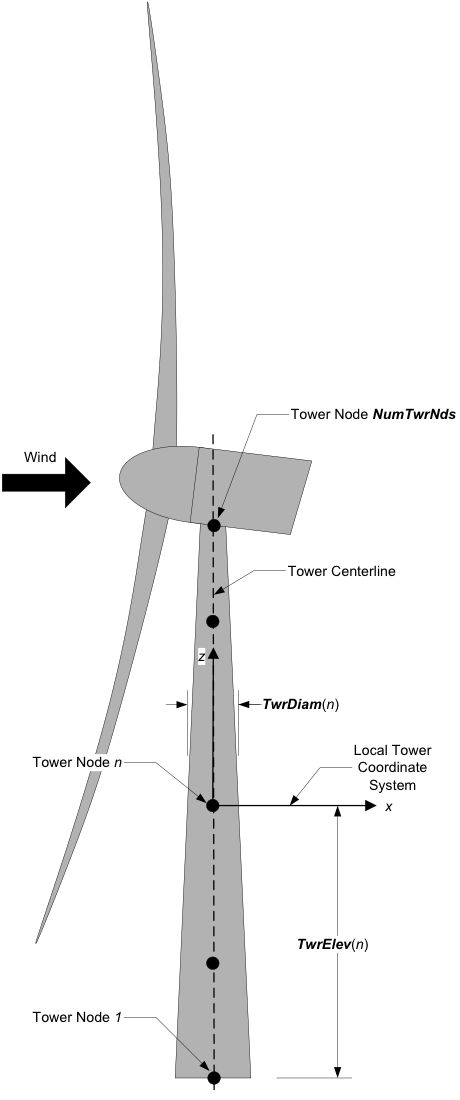
Fig. 4.5 AeroDyn Tower Geometry
The OutList section controls output quantities generated by
AeroDyn. Enter one or more lines containing quoted strings that in turn
contain one or more output parameter names. Separate output parameter
names by any combination of commas, semicolons, spaces, and/or tabs. If
you prefix a parameter name with a minus sign, “-”, underscore, “_”, or
the characters “m” or “M”, AeroDyn will multiply the value for that
channel by –1 before writing the data. The parameters are written in the
order they are listed in the input file. AeroDyn allows you to use
multiple lines so that you can break your list into meaningful groups
and so the lines can be shorter. You may enter comments after the
closing quote on any of the lines. Entering a line with the string “END”
at the beginning of the line or at the beginning of a quoted string
found at the beginning of the line will cause AeroDyn to quit scanning
for more lines of channel names. Blade and tower node-related quantities
are generated for the requested nodes identified through the
BlOutNd and TwOutNd lists above. If AeroDyn encounters an
unknown/invalid channel name, it warns the users but will remove the
suspect channel from the output file. Please refer to Appendix E for a
complete list of possible output parameters.
4.3.3.18. Nodal Outputs
In addition to the named outputs in Section 4.3.3.17 above, AeroDyn allows
for outputting the full set blade node motions and loads (tower nodes
unavailable at present). Please refer to the AeroDyn_Nodes tab in the
Excel file OutListParameters.xlsx
for a complete list of possible output parameters.
This section follows the END statement from normal Outputs section described above, and includes a separator description line followed by the following options.
BldNd_BladesOut specifies the number of blades to output. Possible values are 0 through the number of blades AeroDyn is modeling. If the value is set to 1, only blade 1 will be output, and if the value is 2, blades 1 and 2 will be output.
BldNd_BlOutNd specifies which nodes to output (on all blades selected for output). Valid entries are “ALL” (all blade nodes), “TIP” (only the last blade node), “ROOT”, (only the first blade node), or a list of numbers corresponding to the node to output; valid numbers are 1 through the number of blade nodes AeroDyn is modeling on each blade.
The OutList section controls the nodal output quantities generated by AeroDyn. In this section, the user specifies the name of the channel family to output. The output name for each channel is then created internally by AeroDyn by combining the blade number, node number, and channel family name. For example, if the user specifies AxInd as the channel family name, the output channels will be named with the convention of B\(\mathbf{\beta}\)N###AxInd where \(\mathbf{\beta}\) is the blade number, and ### is the three digit node number.
Sample Nodal Outputs section
This sample includes the END statement from the regular outputs section.
 1END of input file (the word "END" must appear in the first 3 columns of this last OutList line)
 2---------------------- NODE OUTPUTS --------------------------------------------
 3          3   BldNd_BladesOut  - Number of blades to output all node information at.  Up to number of blades on turbine. (-)
 4      "ALL"   BldNd_BlOutNd   - Specify a portion of the nodes to output. {"ALL", "Tip", "Root", or a list of node numbers} (-)
 5              OutList     - The next line(s) contains a list of output parameters.  See OutListParameters.xlsx, AeroDyn_Nodes tab for a listing of available output channels, (-)
 6"VUndx"     - x-component of undisturbed wind velocity at each node
 7"VUndy"     - y-component of undisturbed wind velocity at each node
 8"VUndz"     - z-component of undisturbed wind velocity at each node
 9"VDisx"     - x-component of disturbed wind velocity at each node
10"VDisy"     - y-component of disturbed wind velocity at each node
11"VDisz"     - z-component of disturbed wind velocity at each node
12"STVx"      - x-component of structural translational velocity at each node
13"STVy"      - y-component of structural translational velocity at each node
14"STVz"      - z-component of structural translational velocity at each node
15"VRel"      - Relvative wind speed at each node
16"DynP"      - Dynamic pressure at each node
17"Re"        - Reynolds number (in millions) at each node
18"M"         - Mach number at each node
19"Vindx"     - Axial induced wind velocity at each node
20"Vindy"     - Tangential induced wind velocity at each node
21"AxInd"     - Axial induction factor at each node
22"TnInd"     - Tangential induction factor at each node
23"Alpha"     - Angle of attack at each node
24"Theta"     - Pitch+Twist angle at each node
25"Phi"       - Inflow angle at each node
26"Curve"     - Curvature angle at each node
27"Cl"        - Lift force coefficient at each node
28"Cd"        - Drag force coefficient at each node
29"Cm"        - Pitching moment coefficient at each node
30"Cx"        - Normal force (to plane) coefficient at each node
31"Cy"        - Tangential force (to plane) coefficient at each node
32"Cn"        - Normal force (to chord) coefficient at each node
33"Ct"        - Tangential force (to chord) coefficient at each node
34"Fl"        - Lift force per unit length at each node
35"Fd"        - Drag force per unit length at each node
36"Mm"        - Pitching moment per unit length at each node
37"Fx"        - Normal force (to plane) per unit length at each node
38"Fy"        - Tangential force (to plane) per unit length at each node
39"Fn"        - Normal force (to chord) per unit length at each node
40"Ft"        - Tangential force (to chord) per unit length at each node
41"Clrnc"     - Tower clearance at each node (based on the absolute distance to the nearest point in the tower from blade node B#N# minus the local tower radius, in the deflected configuration); please note that this clearance is only approximate because the calculation assumes that the blade is a line with no volume (however, the calculation does use the local tower radius); when blade node B#N# is above the tower top (or below the tower base), the absolute distance to the tower top (or base) minus the local tower radius, in the deflected configuration, is output
42"Vx"        - Local axial velocity
43"Vy"        - Local tangential velocity
44"GeomPhi"   - Geometric phi? If phi was solved using normal BEMT equations, GeomPhi = 1; otherwise, if it was solved geometrically, GeomPhi = 0.
45"Chi"       - Skew angle (used in skewed wake correction) -- not available for OLAF
46"UA_Flag"   - Flag indicating if UA is turned on for this node. -- not available for OLAF
47"CpMin"     - Pressure coefficient
48"SgCav"     - Cavitation number
49"SigCr"     - Critical cavitation number
50"Gam"       - Gamma -- circulation on blade
51"Cl_Static" - Static portion of lift force coefficient at each node, without  unsteady effects -- not available for BEMT/DBEMT
52"Cd_Static" - Static portion of drag force coefficient at each node, without unsteady effects -- not available for BEMT/DBEMT
53"Cm_Static" - Static portion of pitching moment coefficient at each node, without unsteady effects -- not available for BEMT/DBEMT
54"Uin"       - Axial induced velocity in rotating hub coordinates. Axial aligned with hub axis.     rotor plane polar hub rotating coordinates
55"Uit"       - Tangential induced velocity in rotating hub coordinates. Tangential to the rotation plane. Perpendicular to blade aziumth.     rotor plane polar hub rotating coordinates
56"Uir"       - Radial induced velocity in rotating hub coordinates. Radial outwards in rotation plane. Aligned with blade azimuth.     rotor plane polar hub rotating coordinates
57"Fbn"       - Buoyant force normal to chord per unit length at each node
58"Fbt"       - Buoyant force tangential to chord per unit length at each node
59"Fbs"       - Buoyant spanwise force per unit length at each node
60"Mbn"       - Buoyant moment normal to chord per unit length at each node
61"Mbt"       - Buoyant moment tangential to chord per unit length at each node
62"Mbs"       - Buoyant spanwise moment per unit length at each node
63END of input file (the word "END" must appear in the first 3 columns of this last OutList line)
64---------------------------------------------------------------------------------------
4.3.3.19. Tail fin outputs
The tail fin outputs are:
TFinAlpha (deg): Angle of attack at the reference point of the fin
TFinDynP (Pa): Dynamic pressure at the reference point of the fin
TFinM (-): Mach number at the reference point of the fin
TFinRe (-): Reynolds number at the reference point of the fin
TFinVrel (m/s): Orthogonal relative velocity norm (\(V_{\text{rel},\perp}\)) at the reference point of the fin
TFinVdisxi (m/s): Disturbed velocity (x) at the reference point of the fin in the inertial coordinate system
TFinVdisyi (m/s): Disturbed velocity (y) at the reference point of the fin in the inertial coordinate system
TFinVdiszi (m/s): Disturbed velocity (z) at the reference point of the fin in the inertial coordinate system
TFinVrelxi (m/s): Relative velocity (x) at the reference point of the fin in the inertial coordinate system
TFinVrelyi (m/s): Relative velocity (y) at the reference point of the fin in the inertial coordinate system
TFinVrelzi (m/s): Relative velocity (z) at the reference point of the fin in the inertial coordinate system
TFinVundxi (m/s): Undisturbed velocity (x) at the reference point of the fin in the inertial coordinate system
TFinVundyi (m/s): Undisturbed velocity (y) at the reference point of the fin in the inertial coordinate system
TFinVundzi (m/s): Undisturbed velocity (z) at the reference point of the fin in the inertial coordinate system
TFinSTVxi (m/s): Structural velocity (x) at the reference point of the fin in the inertial coordinate system
TFinSTVyi (m/s): Structural velocity (y) at the reference point of the fin in the inertial coordinate system
TFinSTVzi (m/s): Structural velocity (z) at the reference point of the fin in the inertial coordinate system
TFinFxi (N) : Aerodynamic force (x) at the reference point of the fin in the inertial coordinate system
TFinFyi (N) : Aerodynamic force (y) at the reference point of the fin in the inertial coordinate system
TFinFzi (N) : Aerodynamic force (z) at the reference point of the fin in the inertial coordinate system
TFinMxi (Nm): Aerodynamic moment (x) at the reference point of the fin in the inertial coordinate system
TFinMyi (Nm): Aerodynamic moment (y) at the reference point of the fin in the inertial coordinate system
TFinMzi (Nm): Aerodynamic moment (z) at the reference point of the fin in the inertial coordinate system
4.3.3.19.1. Airfoil Data Input File
The airfoil data input files themselves (one for each airfoil) include tables containing coefficients of lift force, drag force, and pitching moment versus AoA, as well as UA model parameters. In these files, any line whose first non-blank character is an exclamation point (!) is ignored (for inserting comment lines). The non-comment lines should appear within the file in order, but comment lines may be intermixed as desired for reading clarity. A sample airfoil data input file is given in Section 4.3.11.
InterpOrd is the order the static airfoil data is interpolated
when AeroDyn uses table look-up to find the lift-, drag-, and optional
pitching-moment, and minimum pressure coefficients as a function of AoA.
When InterpOrd is 1, linear interpolation is used; when
InterpOrd is 3, the data will be interpolated with cubic splines;
if the keyword DEFAULT is entered in place of a numerical value,
InterpOrd is set to 1.
RelThickness is the non-dimensional thickness of the airfoil
(thickness over chord ratio), expressed as a fraction (not a percentage),
typically between 0.1 and 1.
The parameter is currently used when UA_Mod=7, but might be used more in the future.
The default value of 0.2 if provided for convenience.
NonDimArea is the nondimensional airfoil area (normalized by the
local BlChord squared), but is currently unused by AeroDyn.
NumCoords is the number of points to define the exterior shape of
the airfoil, plus one point to define the aerodynamic center, and
determines the number of rows in the subsequent table; NumCoords
must be exactly zero or greater than or equal to three. For each point,
the nondimensional X and Y coordinates are specified in the table,
X_Coord and Y_Coord (normalized by the local
BlChord). The first point must always locate the aerodynamic
center (reference point for the airfoil lift and drag forces, likely not
on the surface of the airfoil); the remaining points should define the
exterior shape of the airfoil. The airfoil shape is currently unused by
AeroDyn, but when AeroDyn is coupled to OpenFAST, the airfoil shape will be
used by OpenFAST for blade surface visualization when enabled.
BL_file is the name of the file containing boundary-layer characteristics
of the profile. It is ignored if the aeroacoustic module is not used.
This parameter may also be omitted from the file if the aeroacoustic module is not used.
Specify the number of Reynolds number- or aerodynamic-control
setting-dependent tables of data for the given airfoil via the
NumTabs setting. The remaining parameters in the
airfoil data input files are entered separately for each table.
Re and UserProp are the Reynolds number (in millions) and
aerodynamic-control (or user property) setting for the included table.
These values are used only when the AFTabMod parameter in the
primary AeroDyn input file is set to use 2D interpolation based on
Re or UserProp. If 1D interpolation (based only on angle of attack)
is used, only the first table in the file will be used.
Set InclUAdata to TRUE if you are including the UA model
parameters. If this is set to FALSE, all of the UA model parameters
will be determined by the code. Any lines that are missing from this section
will have their values determined by the code, either using a default value
or calculating it based on the polar coefficient data in the airfoil table:
alpha0specifies the zero-lift AoA (in degrees);alpha1specifies the AoA (in degrees) larger thanalpha0for which f equals 0.7; approximately the positive stall angle; This parameter is used whenflookup=falseand when determining a default value ofCn1.alpha2specifies the AoA (in degrees) less thanalpha0for which f equals 0.7; approximately the negative stall angle; This parameter is used whenflookup=falseand when determining a default value ofCn2.alphaUpperspecifies the AoA (in degrees) of the upper boundary of fully-attached region of the cn or cl curve. It is used to compute the separation function whenUA_Mod=5.alphaLowerspecifies the AoA (in degrees) of the lower boundary of fully-attached region of the cn or cl curve. It is used to compute the separation function whenUA_Mod=5. (The separation function will have a value of 1 betweenalphaUpperandalphaLower.)eta_eis the recovery factor and typically has a value in the range [0.85 to 0.95] forUA_Mod = 1; if the keywordDEFAULTis entered in place of a numerical value,eta_eis set to 0.9 forUA_Mod = 1, buteta_eis set to 1.0 for otherUA_Modvalues and wheneverFLookup = TRUE;C_nalphais the slope of the 2D normal force coefficient curve in the linear region;C_lalphais the slope of the 2D normal lift coefficient curve in the linear region; Used forUA_Mod=4,6.T_f0is the initial value of the time constant associated with Df in the expressions of Df and f’; if the keywordDEFAULTis entered in place of a numerical value,T_f0is set to 3.0;T_V0is the initial value of the time constant associated with the vortex lift decay process, used in the expression ofCvn; it depends on Reynolds number, Mach number, and airfoil; if the keywordDEFAULTis entered in place of a numerical value,T_V0is set to 6.0;T_pis the boundary-layer leading edge pressure gradient time constant in the expression for Dp and should be tuned based on airfoil experimental data; if the keywordDEFAULTis entered in place of a numerical value,T_pis set to 1.7;T_VLis the time constant associated with the vortex advection process, representing the nondimensional time in semi-chords needed for a vortex to travel from the leading to trailing edges, and used in the expression of Cvn; it depends on Reynolds number, Mach number (weakly), and airfoil; valued values are in the range [6 to 13]; if the keywordDEFAULTis entered in place of a numerical value,T_VLis set to 11.0;b1is a constant in the expression of \(\phi_\alpha^c\) and \(\phi_q^c\); this value is relatively insensitive for thin airfoils, but may be different for turbine airfoils; if the keywordDEFAULTis entered in place of a numerical value,b1is set to 0.14, based on experimental results;b2is a constant in the expression of \(\phi_\alpha^c\) and \(\phi_q^c\); this value is relatively insensitive for thin airfoils, but may be different for turbine airfoils; if the keywordDEFAULTis entered in place of a numerical value,b2is set to 0.53, based on experimental results;b5is a constant in the expression of \(K^{'''}_q\), \(Cm_q^{nc}\), and \(K_{m_q}\); if the keywordDEFAULTis entered in place of a numerical value,b5is set to 5, based on experimental results;A1is a constant in the expression \(\phi_\alpha^c\) and \(\phi_q^c\); this value is relatively insensitive for thin airfoils, but may be different for turbine airfoils; if the keywordDEFAULTis entered in place of a numerical value,A1is set to 0.3, based on experimental results;A2is a constant in the expression \(\phi_\alpha^c\) and \(\phi_q^c\); this value is relatively insensitive for thin airfoils, but may be different for turbine airfoils; if the keywordDEFAULTis entered in place of a numerical value,A2is set to 0.7, based on experimental results;A5is a constant in the expression \(K^{'''}_q\), \(Cm_q^{nc}\), and \(K_{m_q}\); if the keywordDEFAULTis entered in place of a numerical value,A5is set to 1, based on experimental results;S1is the constant in the best fit curve of f foralpha0\(\le\) AoA \(\le\)alpha1forUA_Mod = 1(and is unused otherwise); by definition, it depends on the airfoil;S2is the constant in the best fit curve of f for AoA >alpha1forUA_Mod = 1(and is unused otherwise); by definition, it depends on the airfoil;S3is the constant in the best fit curve of f foralpha2\(\le\) AoA \(\le\)alpha0forUA_Mod = 1(and is unused otherwise); by definition, it depends on the airfoil;S4is the constant in the best fit curve of f for AoA <alpha2forUA_Mod = 1(and is unused otherwise); by definition, it depends on the airfoil;Cn1is the critical value of \(C^{\prime}_n\) at leading-edge separation for positive AoA and should be extracted from airfoil data at a given Reynolds number and Mach number;Cn1can be calculated from the static value of Cn at either the break in the pitching moment or the loss of chord force at the onset of stall;Cn1is close to the condition of maximum lift of the airfoil at low Mach numbers;Cn2is the critical value of \(C^{\prime}_n\) at leading-edge separation for negative AoA and should be extracted from airfoil data at a given Reynolds number and Mach number;Cn2can be calculated from the static value of Cn at either the break in the pitching moment or the loss of chord force at the onset of stall;Cn2is close to the condition of maximum lift of the airfoil at low Mach numbers;St_shis the Strouhal’s shedding frequency; if the keywordDEFAULTis entered in place of a numerical value,St_shis set to 0.19;Cd0is the drag-force coefficient at zero-lift AoA;Cm0is the pitching-moment coefficient about the quarter-chord location at zero-lift AoA, positive for nose up;k0is a constant in the best fit curve of \(\hat{x}_{cp}\) and equals for \(\hat{x}_{AC}-0.25\)UA_Mod = 1(and is unused otherwise);k1is a constant in the best fit curve of \(\hat{x}_{cp}\) forUA_Mod = 1(and is unused otherwise);k2is a constant in the best fit curve of \(\hat{x}_{cp}\) forUA_Mod = 1(and is unused otherwise);k3is a constant in the best fit curve of \(\hat{x}_{cp}\) forUA_Mod = 1(and is unused otherwise);k1_hatis a constant in the expression of Cc due to leading-edge vortex effects forUA_Mod = 1(and is unused otherwise);x_cp_baris a constant in the expression of \(\hat{x}_{cp}^{\nu}\) forUA_Mod = 1(and is unused otherwise); if the keywordDEFAULTis entered in place of a numerical value,x_cp_baris set to 0.2; andUACutOutis the AoA (in degrees) in absolute value above which UA are disabled; if the keywordDEFAULTis entered in place of a numerical value,UACutOutis set to 45.UACutOut_deltais the AoA difference (in degrees) which, together withUACutOutdetermines when unsteady aero begins to turn off; if the keywordDEFAULTis entered in place of a numerical value,UACutOut_deltais set to 5 degrees. The unsteady solution is used at angles of attack less thanUACutOut - UACutout_deltadegrees. AboveUACutout, the steady solution is used (i.e., UA is disabled). The steady and unsteady solutions are blended between those two angles.filtCutOffis the cut-off reduced frequency of the low-pass filter applied to the AoA input to UA, as well as to the pitch rate and pitch acceleration derived from AoA within UA; if the keywordDEFAULTis entered in place of a numerical value,filtCutOffis set to 0.5. This non-dimensional value corresponds to a frequency of \(\frac{U \times \mathrm{filtCutOff}}{\pi \times \mathrm{chord}}\) Hz.
NumAlf is the number of distinct AoA entries and determines the
number of rows in the subsequent table of static airfoil coefficients;
NumAlf must be greater than or equal to one (NumAlf = 1
implies constant coefficients, regardless of the AoA).
AeroDyn will
interpolate on AoA using the data provided via linear interpolation or via cubic
splines, depending on the setting of input InterpOrd above.
If AFTabMod is set to 1, only the first airfoil table in each file
will be used. If AFTabMod is set to 2, AeroDyn will find the
airfoil tables that bound the computed Reynolds number,
and linearly interpolate between the tables, using the logarithm of the Reynolds numbers.
If AFTabMod is set to 3, it will find the bounding airfoil
tables based on the UserProp field and linearly interpolate the tables
based on it. Note that OpenFAST currently sets the UserProp input value to 0
unless the DLL controller is used and sets the value,
so using this feature may require a code change.
For each AoA, you must set the AoA (in degrees), alpha, the lift-force
coefficient, Coefs(:,1), the drag-force coefficient,
Coefs(:,2), and optionally the pitching-moment coefficient,
Coefs(:,3), and minimum pressure coefficient,
Coefs(:,4), but the column order depends on the settings of
InCol_Alfa, InCol_Cl, InCol_Cd, InCol_Cm,
and InCol_Cpmin in the AIRFOIL INFORMATION section of the AeroDyn
primary input file. AoA must be entered in monotonically increasing
order—from lowest to highest AoA; the first row should be for AoA =
–180 degrees and the last should be for AoA = +180 (unless NumAlf = 1, in
which case AoA is unused). If pitching-moment terms are neglected with
UseBlCm = FALSE in the ROTOR/BLADE PROPERTIES section of the
AeroDyn primary input file, the column containing pitching-moment
coefficients may be absent from the file. Likewise, if the cavitation
check is neglected with CavitCheck = FALSE in the GENERAL OPTIONS
section of the AeroDyn primary input file, the column containing the
minimum pressure coefficients may be absent from the file.
4.3.3.19.2. Blade Data Input File
The blade data input file contains the nodal discretization, geometry, twist, chord, airfoil identifier, and buoyancy/added mass/fluid inertia properties for a blade. Separate files are used for each blade, which permits modeling of aerodynamic imbalances. A sample blade data input file is given in Section 4.3.11.
The input file begins with two lines of header information which is for your use, but is not used by the software.
NumBlNds is the user-specified number of blade analysis nodes and
determines the number of rows in the subsequent table (after two table
header lines). NumBlNds must be greater than or equal to two; the
higher the number, the finer the resolution and longer the computational
time; we recommend that NumBlNds be between 10 and 20 to balance
accuracy with computational expense. Even though NumBlNds is
defined in each blade file, all blades must have the same number of
nodes. For each node:
BlSpnspecifies the local span of the blade node along the (possibly preconed) blade-pitch axis from the root;BlSpnmust be entered in monotonically increasing order—from the most inboard to the most outboard—and the first node must be zero, and when AeroDyn is coupled to OpenFAST, the last node should be located at the blade tip;BlCrvACspecifies the local out-of-plane offset (when the blade-pitch angle is zero) of the aerodynamic center (reference point for the airfoil lift and drag forces), normal to the blade-pitch axis, as a result of blade curvature;BlCrvACis positive downwind; upwind turbines have negativeBlCrvACfor improved tower clearance;BlSwpACspecifies the local in-plane offset (when the blade-pitch angle is zero) of the aerodynamic center (reference point for the airfoil lift and drag forces), normal to the blade-pitch axis, as a result of blade sweep; positiveBlSwpACis opposite the direction of rotation;BlCrvAngspecifies the local angle (in degrees) from the blade-pitch axis of a vector normal to the plane of the airfoil, as a result of blade out-of-plane curvature (when the blade-pitch angle is zero);BlCrvAngis positive downwind; upwind turbines have negativeBlCrvAngfor improved tower clearance;BlTwistspecifies the local aerodynamic twist angle (in degrees) of the airfoil; it is the orientation of the local chord about the vector normal to the plane of the airfoil, positive to feather, leading edge upwind; the blade-pitch angle will be added to the local twist;BlChordspecifies the local chord length;BlAFIDspecifies which airfoil data the local blade node is associated with; valid values are numbers between 1 andNumAFfiles(corresponding to a row number in the airfoil file table in the AeroDyn primary input file); multiple blade nodes can use the same airfoil data;t_cspecifies the blade thickness-to-chord ratio, used to calculate the reference cross-sectional area for added mass and fluid inertia loads, cannot be less than 0;BlCbspecifies the blade buoyancy coefficient, defined as the local cross-sectional area of the blade divided by the area of a circle with diameter equal toBlChord; to neglect buoyant loads on the blade, setBlCbto 0; since the blades and hub are joined elements, blade buoyancy should be included if hub buoyancy is included, and vice versa;BlCenBnspecifies the offset of the blade center of buoyancy from the aerodynamic center in the direction normal to the chord (positive pointing toward the suction side of the blade);BlCenBtspecifies the offset of the blade center of buoyancy from the aerodynamic center in the direction tangential to the chord (positive pointing toward the trailing edge of the blade);BlCpnspecifies the blade normal-to-chord dynamic pressure coefficient; to neglect normal-to-chord fluid inertia loads on the blade, setBlCpnto 0;BlCptspecifies the blade tangential-to-chord dynamic pressure coefficient; to neglect tangential-to-chord fluid inertia loads on the blade, setBlCptto 0;BlCanspecifies the blade normal-to-chord added mass coefficient, cannot be less than 0; to neglect normal-to-chord added mass loads on the blade, setBlCanto 0;BlCatspecifies the blade tangential-to-chord added mass coefficient, cannot be less than 0; to neglect tangential-to-chord added mass loads on the blade, setBlCatto 0; andBlCamspecifies the blade pitch added mass coefficient, cannot be less than 0; to neglect pitch added mass loads on the blade, setBlCamto 0.
See Fig. 4.6. Twist is shown in Fig. 4.4 of Section 4.3.11.
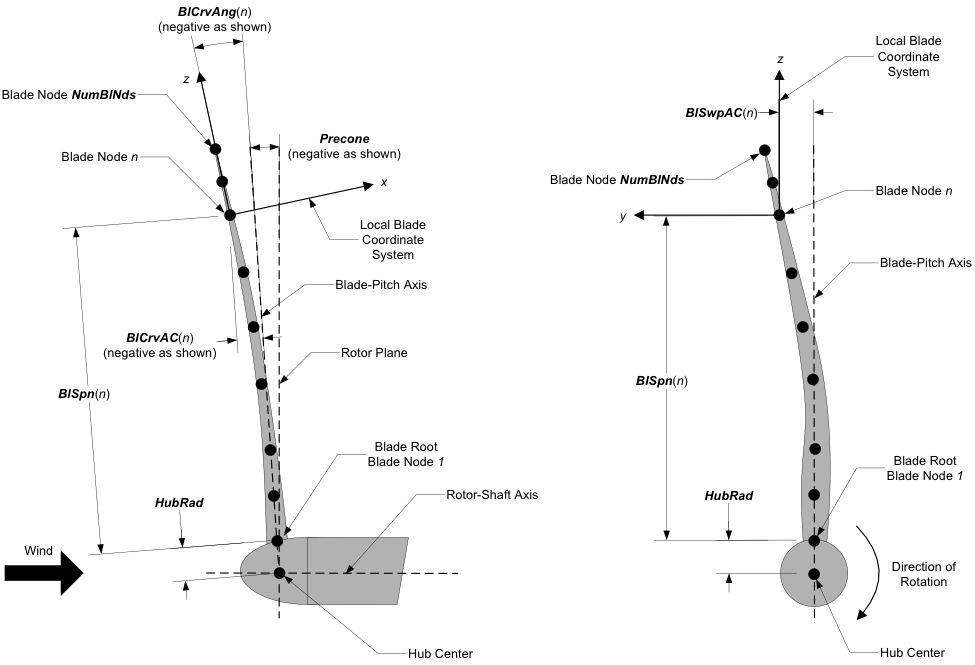
Fig. 4.6 AeroDyn Blade Geometry – Left: Side View; Right: Front View (Looking Downwind)
4.3.3.19.3. Tail fin input file
An example of tail fin input file is given below:
------- TAIL FIN AERODYNAMICS INPUT FILE--------------------------------------------
Comment
======  General inputs =============================================================
1         TFinMod     - Tail fin aerodynamics model {0: none, 1: polar-based, 2: USB-based} (switch)
0.3       TFinArea    - Tail fin planform area (m^2)
10.,0.,0. TFinRefP_n  - Undeflected position of the tail fin reference point wrt the tower top (m)
0.,0.,0.  TFinAngles  - Tail fin chordline skew, tilt, and bank angles about the reference point (degrees)
0         TFinIndMod  - Model for induced velocity calculation {0: none, 1:rotor-average} (switch)
====== Polar-based model ================================ [used only when TFinMod=1]
1         TFinAFID - Index of Tail fin airfoil number [1 to NumAFfiles]
0.5       TFinChord   - Tail fin chord (m)
====== Unsteady slender body model  ===================== [used only when TFinMod=2]
0.9           TFinKp        - Tail fin potential flow coefficient (-)
0.3,0.1,0.1   TFinSigma     - Tail fin empirical constant for vortex separation functions (1/deg)
40,60,60      TFinAStar     - Tail fin initial angles for vortex separation functions (deg)
3.1416        TFinKv        - Tail fin vortex lift coefficient (-)
1.3           TFinCDc       - Tail fin drag coefficient (-)
4.3.3.20. General inputs
TFinMod is a switch to select a model for the tail fin aerodynamics:
0) none (the aerodynamic forces are zero), 1) polar-based, 2) USB-based (see Section 4.3.9).
(switch)
TFinArea is the area of the tail fin. (m^2)
This is the plan form area of the tail fin plate used to relate the local dynamic pressure and airfoil
coefficients to aerodynamic loads. This value must not be negative and is only used when
TFinMod is set to 1. (m^2)
TFinRefP_n is the undeflected position (\(x_{\text{ref},x_n},x_{\text{ref},y_n}, x_{\text{ref},z_n}\)) of the tail fin from the tower top in nacelle coordinates.
(formerly defined using TFinCPxn, TFinCPyn, TFinCPzn).
The distances defines the configuration for a furl angle of zero.
For a typical upwind wind turbine,
\(x_n\), is positive downwind,
\(y_n\), is positive to the left when looking downwind, and
\(z_n\), is positive upward when looking downwind.
See Fig. 4.48 and Fig. 4.10.
(m)
TFinAngles are the angles (\(\theta_\text{skew},\theta_\text{tilt}, \theta_\text{bank}\)) of the tail fin
(formerly defined as TFinSkew, TFinTilt, TFinBank).
See Fig. 4.48 and Fig. 4.10.
These angles define the chordline at a furl angle of zero, where the chordline is assumed to be passing through the reference point.
\(\theta_\text{skew}\) is the skew angle of the tail fin chordline in the nominally horizontal plane.
Positive skew orients the nominal horizontal projection of the tail fin chordline about the \(z_n\)-axis.
The aforementioned chordline is the chordline passing through the tail fin reference point.
This value must be greater than -180 and less than or equal to 180 degrees.
\(\theta_\text{tilt}\) is the tilt angle of the tail fin chordline from the nominally horizontal plane.
This value must be between -90 and 90 degrees (inclusive).
Positive tilt means that the trailing edge of the tail fin is higher than the leading edge.
\(\theta_\text{bank}\) is the bank angle of the tail fin plane about the tail fin chordline.
This value must be greater than -180 and less than or equal to 180 degrees.
(deg)
TFinIndMod
Switch to select a model for the calculation of the velocity induced by the rotor and its wake on the tailfin (not the induced velocity from the tailfin wing).
The options available are:
0) none (the induced velocity is zero)
1) rotor-average (using the average induced velocity across all blades and blade nodes)
(see Section 4.3.9). (switch)
4.3.3.21. Polar-based model inputs
TFinAFID
This integer tells AeroDyn which of the input airfoil files (AFNames) is assigned to the tail fin. For
instance, a value of 2 means that the tail fin will use AFNames(2) for the local tail fin airfoil.
This value must be
between 1 and NumAFfiles and is only used when TFinMod is set to 1. (-)
4.3.3.22. Unsteady slender body (USB) model inputs
Refer to Section 4.3.9 and [ad-HWS23] for guidance on how to select parameters for the unsteady slender body theory based model.
TFinKp
Potential lift coefficient for unsteady aerodynamics. TFinKp is used to calculate the potential flow contribution to the unsteady aerodynamic force on the tail fin.
TFinSigma
Tail fin empirical constants characterizing the decay of separation functions used in the unsteady aerodynamic model. The separation functions and their dependence on TFinSigma are described in Section 4.3.9.
TFinAStar
Tail fin characteristics angles for separation functions used in the unsteady aerodynamic model. The separation functions and their dependence on TFinAStar are described in Section 4.3.9.
TFinKv
Vortex lift coefficient for unsteady aerodynamics. TFinKv is used to calculate the vortex flow contribution to the unsteady aerodynamic force on the tail fin.
TFinCDc
Tail fin drag coefficient used for unsteady aerodynamic model. The drag on the tail fin significantly contributes to the normal force at high yaw angles.