4.10.1. Coordinate systems
For the coordinates system not detailed in subsections below, please refer to the following references:
OpenFAST_coords.pdf: Presentation from 2024 overviewing some coordinate systems in OpenFAST.Technical report on FAST_AD and modeling of the UAE wind turbine (in section 3)
FASTCoordinateSystems.doc: Documents the transformation matrices relating each coordinate system in OpenFAST. Unfortunately, there are no pictures in this document that diagram these coordinate systems. They can hopefully be visualized by means of the transformation matrices.
4.10.1.1. Rotor-Furl coordinate system
The rotor-furl DOF allows the user to model the
unusual configuration of a bearing that permits the
rotor and drivetrain to rotate about the yawing-portion
of the structure atop the tower. The rotor-furl DOF can
alternatively be used to model torsional flexibility in
the gearbox mounting if the rotor-furl axis is aligned
with the rotor shaft axis. In order to include rotor-
furling in the model, the user must designate the turbine
as a furling machine by setting input Furling from the
primary input file to True. Then, the user must assemble
the furling input file, FurlFile, and use the rotor-furl
flag, RFrlDOF, to enable this feature.
The angular rotor-furl motion takes place about the
rotor-furl axis defined by inputs:
RFrlPnt_n,
RFrlSkew, and RFrlTilt.
available in FurlFile.
The input RFrlPnt_n locate an arbitrary point on the rotor-
furl axis relative to the tower-top. Inputs RFrlSkew
and RFrlTilt then define the angular orientation of the
rotor-furl axis passing through this point.
See Fig. 4.46 for a schematic.
The geometries of the hub and rotor-furl structure mass center, which are both components of the furling- rotor assembly, are defined relative to the tower-top as shown in Fig. 4.47. This definition was chosen in order to avoid having to define a coordinate system in the furling-rotor assembly since such a coordinate system would most likely have an obscure orientation, making it difficult for users to input configuration information relative to it. This definition also avoids the complications involved in having to define geometries differently, depending on whether or not a rotor-furl assembly exists separately from the nacelle, which depends on whether rotor-furl is present or absent in the turbine.
Since the component geometry of the furling-rotor assembly is defined relative to the tower-top, this geometry naturally changes with the rotor-furl angle. In order to avoid having to define different geometries for different rotor-furl positions (for example, variations in the initial rotor-furl angle), ElastoDyn expects the component geometry of the furling-rotor assembly to be defined/input at a rotor-furl angle of zero. As such, the initial rotor-furl angle does not affect the specification of any other rotor-furl geometry. Stated another way, the input geometries for the rotor-furl assembly components define the rotor configuration when the rotor-furl angle is zero regardless of initial rotor-furl position. Users should be clear of this convention when assembling their furling input file.
4.10.1.2. Tail-Furl coordinate system
The tail-furl DOF allows the user to model the unusual
configuration of a bearing that permits the tail to rotate
about the yawing-portion of the structure atop the
tower. In order to include tail-furling in a model,
the user must designate the turbine as a furling machine by
setting the input Furling from the ElastoDyn input file to
True. Then you must assemble the furling input file,
FurlFile, and use the tail-furl flag, TFrlDOF, to enable
this feature.
The angular tail-furl motion takes place about the
tail-furl axis defined by inputs TFrlPnt_n, TFrlSkew, and TFrlTilt available in
FurlFile.
The input TFrlPnt_n locate an arbitrary point on the tail-furl axis
relative to the tower-top.
See Fig. 4.46 for a schematic.
The geometries of the tail boom mass center, tail fin mass center, and tail fin aerodynamic surface, which are all components of the furling-tail assembly, are defined relative to the tower-top as shown in Fig. 4.48. This definition was chosen in order to avoid having to define a coordinate system in the furling-tail assembly since such a coordinate system would most likely have an obscure orientation, making it difficult for users to input configuration information relative to it. This definition also avoids the complications involved in having to define geometries differently, depending on whether or not a tail-furl assembly exists separately from the nacelle, which depends on whether tail-furl is present or absent in the turbine.
Since the component geometry of the furling-tail assembly is defined relative to the tower-top, this geometry naturally changes with the tail-furl angle. In order to avoid having to define different geometries for different tail-furl positions (for example, variations in the initial tail-furl angle), ElastoDyn expects the component geometry of the furling-tail assembly to be defined/input at a tail-furl angle of zero. As such, the initial tail-furl angle does not affect the specification of any other tail-furl geometry. Stated another way, the input geometries for the tail-furl assembly components define the tail configuration when the tail-furl angle is zero regardless of initial tail-furl position. Users should be clear of this convention when assembling their furling input file. Further clarification on this furling geometry convention is provided in the Rotor- Furl section above.
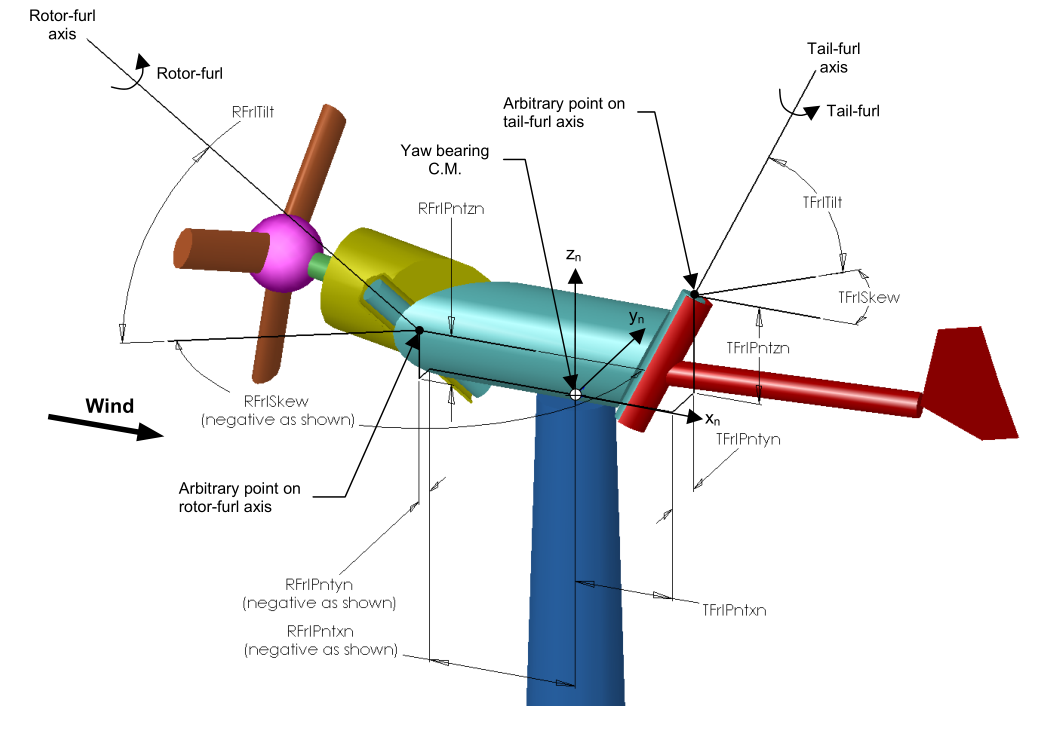
Fig. 4.46 Layout of a three-bladed, upwind, furling turbine: furl axes
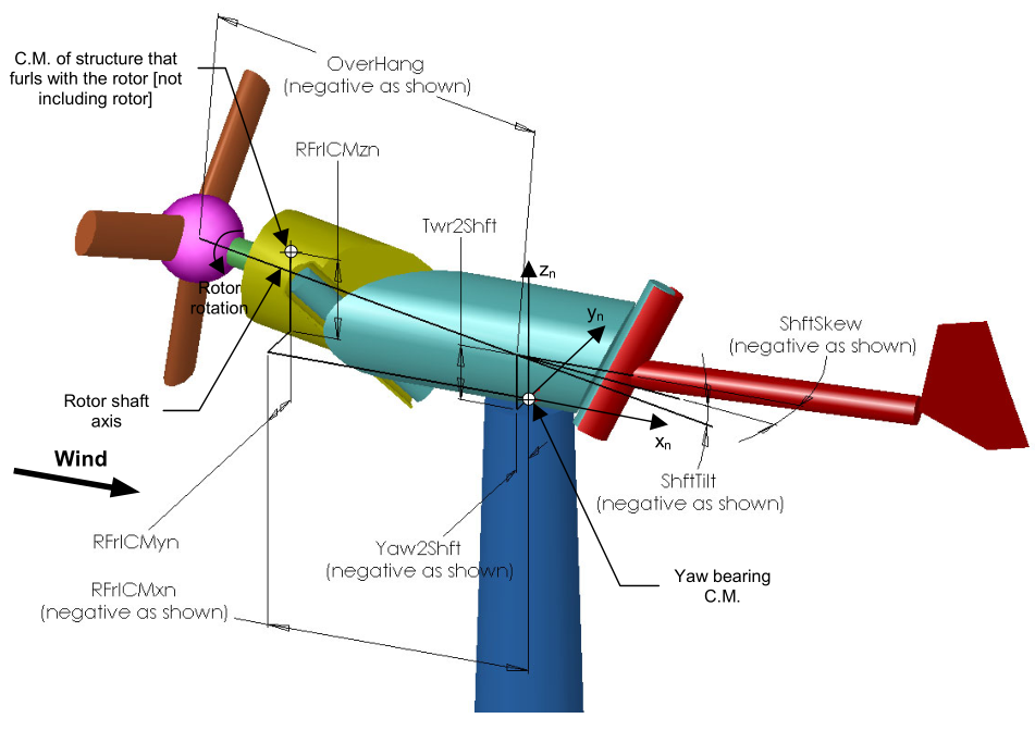
Fig. 4.47 Layout of a three-bladed, upwind, furling turbine: rotor-furl structure
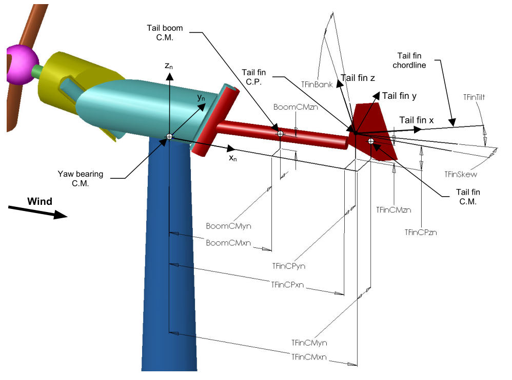
Fig. 4.48 Layout of a three-bladed, upwind, furling turbine: tail-furl structure. NOTE: The tail fin “CP” (center of pressure) parameters are now replaced by the location of the reference point.