4.19.6. Modeling Guidance
This chapter includes modeling guidance for setting up and running a FAST.Farm simulation. This includes guidance on inflow wind generation; low- and high-resolution grid discretization; parameter selection; and solutions for commonly encountered errors.
4.19.6.1. FAST.Farm Setup Overview
This section includes a high-level overview of how to set up ambient inflow and FAST.Farm simulations in particular, the information needed to calculate various parameters, as shown in Fig. 4.64.
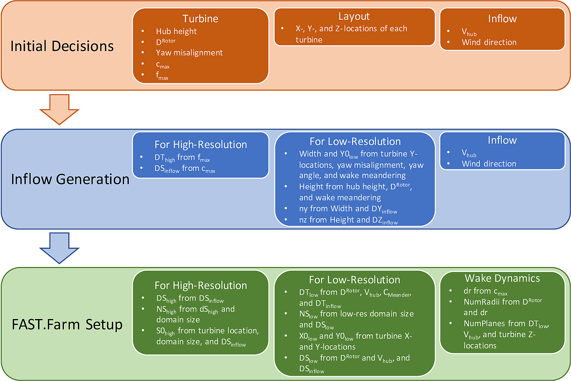
Fig. 4.64 Information flowchart for setting up inflow generation and FAST.Farm simulations. Here, S = X, Y, or Z.
Note that this schematic only includes information relevant to FAST.Farm simulations. Typically, additional inflow information is required to generate inflow and the OpenFAST models. The specific equations that should be used to compute the input parameters are discussed in Section 4.19.6.4. It is highly recommended that the Python notebooks provided in the FAST.Farm tools repository be used when setting up new inflow or a FAST.Farm case. Improperly setting these parameters can lead to common errors and/or excessive interpolation, which should be avoided. Note that this chapter assumes a wind direction of \(0^\circ\)– i.e., ambient wind that propagates along the +X axis of the global inertial frame coordinate system.
When generating a FAST.Farm simulation setup and corresponding inflow, planning is important. Improper planning could results in FAST.Farm errors and/or needing to regenerate the inflow. Values that should be known a priori are:
wind turbine rotor diameter (\(D^\text{Rotor}\));
wind turbine hub height;
maximum turbine chord length (\(c_\text{max}\));
maximum turbine natural frequency (\(f_\text{max}\));
X, Y, and Z locations of all turbines in the wind farm;
desired mean inflow hub-height wind velocity; and
mean inflow wind direction.
The values that must be computed using this information are:
inflow and FAST.Farm domain size (height, width, and length);
FAST.Farm high- and low-resolution domain origin locations (S0_High and S0_Low, where S = X, Y, or Z);
high- and low-resolution temporal discretization values (DT_High and DT_Low);
high- and low-resolution spatial discretization values (DS_High and DS_Low);
number of grid points in the high- and low-resolution domains (NS_High and NS_Low);
actual mean inflow hub-height wind velocity (\(V_\text{hub}\));
additional wake dynamics properties (dr, NumRadii, and NumPlanes).
With this information, inflow generation can begin. Though not required, it is recommended to complete inflow generation before setting up the FAST.Farm simulation. This is because the realized spatial discretization values and/or mean hub height velocity can differ from what is desired. Having the correct values of these parameters leads to less interpolation of the wind data in FAST.Farm simulations, which would otherwise reduce the ambient turbulence.
When setting up the inflow generation, the recommended spatial and temporal discretizations should be used, as discussed in Section 4.19.6.3. If using:
Mod_AmbWind = 1, a high-fidelity must be generated and all discretization values can be specified as the exact desired value.
Mod_AmbWind = 2, a single synthetic inflow (TurbSim or Mann) must be generated using the high-resolution discretization values recommended herein.
Mod_AmbWind = 3, multiple synthetic inflows must be generated. In this case, the recommended high-resolution discretizations should be used for all high-resolution inflows generated. For the low-resolution inflow generation, the recommended high-resolution temporal discretization and low-resolution spatial discretization should be used.
If using synthetic inflow (TurbSim or Mann), the inflow streamwise spatial discretization, DX_Inflow, is not specified by the user, but is instead based on Taylor’s frozen-turbulence assumption. Because the streamwise discretization of the FAST.Farm domain should be based on the inflow streamwise discretization, the user should compute this value using the inflow time step (DT_High) and the advection speed of the synthetic wind data, \(V_\text{Advect}\). The \(V_\text{Advect}\) may differ from the actual wind speed at hub height, \(V_\text{Hub}\), as discussed in Section 4.19.6.2.3, and should be computed directly from the generated synthetic inflow. Therefore, the exact resulting DX_Inflow will not be known until after the inflow has been generated. Additionally, DX_Inflow will likely be much smaller than the desired values of DX_Low and DX_High.
When setting up the FAST.Farm simulation itself, many of the values that were used for inflow generation will be used again here to specify the FAST.Farm domain. Note that this domain specification in FAST.Farm is only needed when using synthetic turbulence inflow. The origin of the low-resolution domain (X0_Low, Y0_Low, and Z0_Low) should be determined based on:
the minimum turbine X- and Y-locations;
turbine yaw misalignment;
inflow wind direction; and
the expected range of wake meandering.
Specifically, X0_Low must accommodate all turbine locations as well as allow enough room to analyze the undisturbed inflow upstream of the wind farm, if desired. Y0_Low must accommodate all turbine locations as well as the horizontal wake meandering. When using TurbSim, which cannot generate wind at ground level, Z0_Low should be close to but above ground level.
The FAST.Farm domain width and height are then computed using:
the turbine locations;
the calculated Y0_Low and Z0_Low values;
the horizontal and vertical meandering distance requirements;
turbine yaw misalignment; and
the inflow wind direction.
The domain length should be based on the streamwise extent of the wind farm and, if desired, allow enough room to analyze the waked outflow downstream of the wind farm.
The low-resolution domain in FAST.Farm (DY_Low and DZ_Low) and number of grid points (NY_Low and NZ_Low) can then be computed using:
the domain width and height;
the lateral and vertical spacing of the generated inflow; and
DY_Inflow and DZ_Inflow.
The low-resolution temporal discretization (DT_Low) should be computed using:
the turbine diameter;
inflow hub-height velocity; and
the inflow temporal discretization.
The streamwise spacing and number of grid points (DX_Low and NX_Low) should also be based on DT_Low and the mean wind speed.
The final domain parameters to calculate are the locations of the high-resolution domains (X0_High, Y0_High, and Z0_High) and the number of grid points required to make up the domains (NX_High, NY_High, and NZ_High). These quantities should be determined from:
DS_High values;
turbine locations; and
the size of the high-resolution domains.
The DS_High values should be selected based on recommended high-resolution domain discretization criteria, discussed in Section 4.19.6.3.
Additional wake dynamics quantities are needed when specifying the FAST.Farm input file, as discussed further in Section 4.19.6.4.2. It is recommended to set dr to \(\le D^\text{Rotor} / 15\); NumRadii on wake diameter and dr; and NumPlanes on DT_Low, inflow hub-height velocity, and the distance between turbine locations.
A sample turbine layout and domain locations are shown in Fig. 4.65.
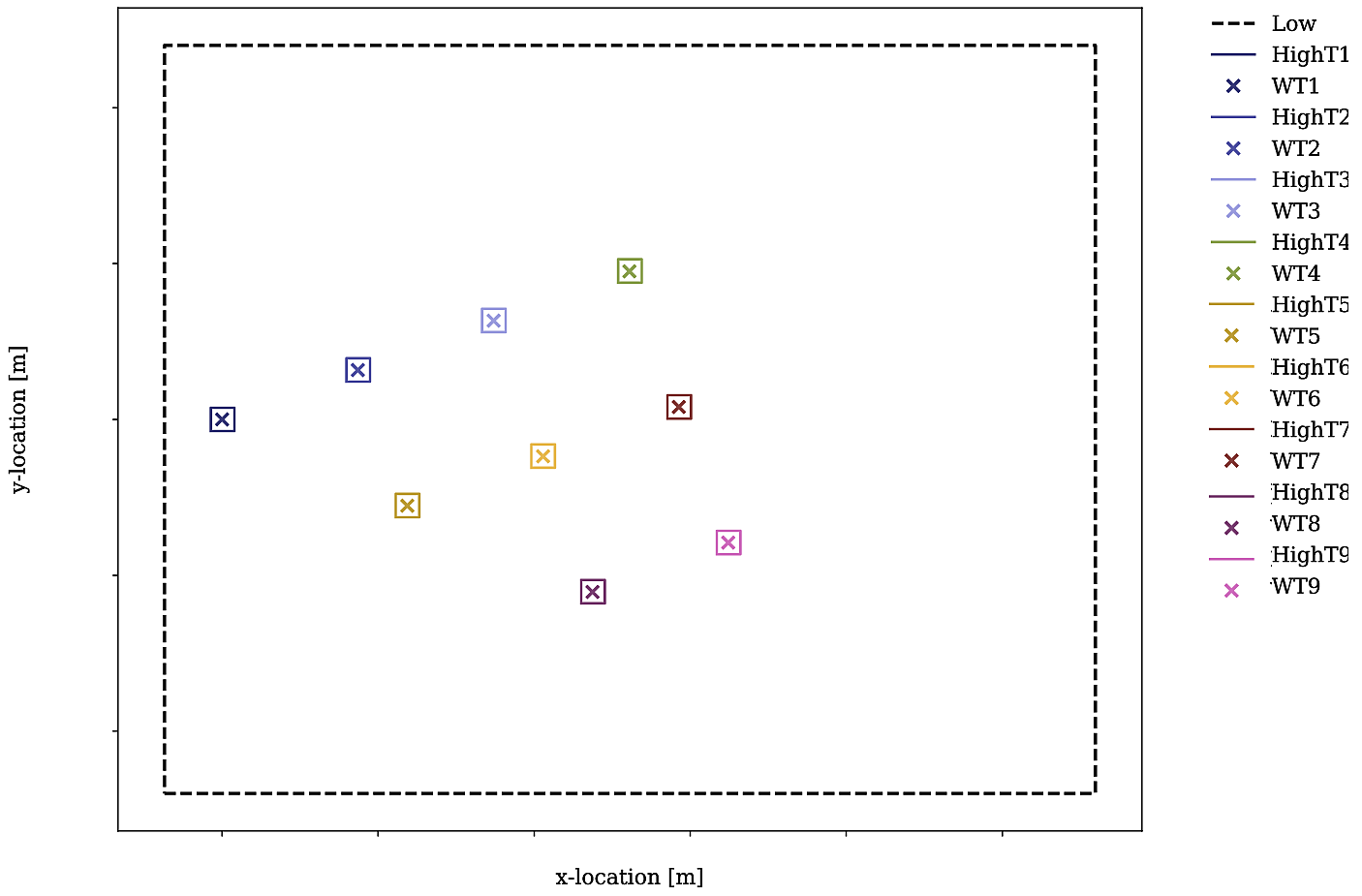
Fig. 4.65 Schematic of example 9-turbine wind farm layout, including low- and high-resolution domains and turbine locations.
4.19.6.2. Inflow Wind Generation
This section includes guidelines by which turbulent inflow should be generated for use with FAST.Farm.
4.19.6.2.1. High-Fidelity Precursor Ambient Inflow
There are many different methods by which high-fidelity precursor ambient inflow can be generated. This section focuses on generating such inflow using SOWFA.
When using SOWFA to generate FAST.Farm precursor inflow, the ABLSolver preprocessor is used. It is important to note the baseline high-fidelity solution is not directly used as inflow for FAST.Farm, but is instead sampled within a specified domain and discretization. This sampling is done through SOWFA and specified in a SOWFA input file. The inflow data are written out in 3D volume VTK-formatted files, as described in Section 4.19.4.3. These are large ASCII-formatted files; as such, decreasing the precision to, e.g., 3 digits is recommended. The domain size and low-resolution domain discretization used for SOWFA simulations is much larger than what is required for FAST.Farm simulations. Therefore, sampling files must be set up to generate boundary conditions for use with FAST.Farm, based on FAST.Farm discretization suggestions detailed in Section 4.19.6.3. Two sampling files are needed: one for the low-resolution sampling for the farm-scale domain and one for the high-resolution sampling for the turbine-scale domains. Each sampling file defines the spatial and temporal discretization that will be used in the FAST.Farm simulations. The low-resolution domain file defines a single low-resolution domain that will be used for the FAST.Farm simulations; the high-resolution domain file defines each high-resolution domain that will be used for the FAST.Farm simulations. Thus, it is important to know exactly where all turbines will be located in the FAST.Farm simulation before generating the inflow. Note that this FAST.Farm sampling step can be computationally expensive. Therefore, it is recommended that users make sure all inputs are correct before executing SOWFA, including turbine locations and discretization levels.
An example Python notebook is provided in the FAST.Farm tools repository to assist in setting up these files for a given FAST.Farm simulation.
4.19.6.2.2. Complex Terrain
Complex terrain, or a time-varying sea-surface elevation for offshore systems, can be modeled in FAST.Farm by providing ambient inflow data that are terrain following, e.g., by modeling the surface boundary condition in an LES precursor. The VTK format used by FAST.Farm is spatially uniform. To accommodate complex terrain or waves with a uniform grid, the wind speed for points below the terrain surface should be set to NaN. Any NaN value will be trapped by FAST.Farm and marked as outside of the domain, and so, unused by calculations within the AWAE module. When the ambient wind inflow is terrain following, the wakes will naturally follow the terrain as well, even though FAST.Farm does not include any explicit models for complex terrain, flow recirculation or separation, or local pressure gradients.
If using a SOWFA inflow precursor, the complex terrain is accounted for in the SOWFA inflow precursor generation, and so, no modification to the vtk files is required to account for complex terrain when sampling for a FAST.Farm simulation.
4.19.6.2.3. Synthetic Turbulence Ambient Inflow
Synthetically generated turbulent inflow can be used in FAST.Farm to accurately predict turbine response and wake dynamics across different atmospheric conditions. There are several ways to achieve this; any method can be used as long as it produces an output file in a format supported by InflowWind. Modeling guidance for TurbSim and the Mann model are discussed next.
4.19.6.2.3.1. TurbSim
When using the NREL tool TurbSim v2, different options are available to drive the synthetic turbulence towards specific desired outcomes, e.g.;
standard or user-defined time-averaged wind profile (shear, veer);
standard or user-defined velocity spectra in three directions (along the wind, u, and transverse, v and w);
standard or user-defined spatial point-to-point coherence; and
standard or user-defined component-to-component correlations (Reynolds stresses).
Additionally, TurbSim v2 allows the user to generate turbulent wind that is consistent with user-defined three-component wind time series at one or more points (i.e., constrained wind). These options can be used separately or in some combination (though user-defined spectra and user-defined time series can not be used together). When defined appropriately, all these methods can result in good statistical comparison of turbine response and wake dynamics between FAST.Farm results and a reference data set, e.g., compared with an LES precursor or physically measured inflow. However, attention must be paid when generating these inflows to ensure atmospheric conditions are modeled properly.
In particular, TurbSim generates wind velocities transversely throughout the domain using u-, v-, and w-spatial-coherence models based on a selection of coherence model equations and their associated parameters. These models and parameters can either be specified explicitly or left as default values in TurbSim. When the IEC spatial-coherence model is selected, spatial coherence is computed using Eq. (4.221) ([ff-Jon14]).
where \(V_\text{Advect}\) is the average wind speed at the hub height
specified in TurbSim, which is also the advection speed in InflowWind;
\(Coh_{i,j_K}\) is the spatial coherence between points \(i\)
and \(j\) for the velocity components \(K=u,v,w\); \(r\) is
the distance between points \(i\) and \(j\); \(a_K\) is the
coherence decrement parameter; and \(b_K\) is the coherence offset
parameter. It was discovered in [ff-Seal19b] that the
use of the IEC coherence model with default coherence parameters
together with the IEC Kaimal spectra results in negligible wake
meandering. This is because the default v- and w-coherence parameters in
TurbSim are set such that \(a_K\) are very large numbers and
\(b_K=0\), effectively resulting in no coherence
(\(Coh_{i,j_K}(f)=0\)) ([ff-Jon14]). 1 This
lack of meandering is nonphysical and will have a nonphysical impact on
the response of downstream turbines. Instead of using the default
values, the v- and w-coherence parameters were specified
in [ff-Seal19b] to identically equal the u-coherence
parameters specified in the IEC standard, such that:
\(SCMod2=SCMod3=IEC\); \(a_K=12.0\) and \(b_K=0.00035273\)
m\(^{-1}\); and
\(CohExp=0.0\). ([ff-Jon14]). Properly setting
spatial coherence parameters for the transverse wind velocity components
is necessary to accurately predict wake meandering. It is also important
to note that, in TurbSim, the \(a_K\) and \(b_K\) values must be
specified within quotation marks (e.g., "12.0 0.00035273") or, at
present, the values are set to \(0\).
When using TurbSim to generate the full-field turbulent wind data for FAST.Farm, one often wants the TurbSim grid to extend well above the hub height to capture vertical wake meandering due to the \(w\) component of turbulence. Because TurbSim requires that HubHt\(> 0.5*\)GridHeight, it is often necessary to specify an artificially high HubHt in TurbSim. To properly set the HubHt parameter, the following equation is suggested:
where \(z_\text{bot}\) is the desired bottom vertical location of the grid (just above ground level) and \(D_\text{grid}=MIN\left( \textbf{GridWidth}, \textbf{GridHeight}\right)\). Note that the HubHt parameter is used by TurbSim as the reference height for the wind speed used (\(V_\text{Advect}\)) to define the wind-speed standard deviations and spatial coherence in the IEC turbulence models, as well as the advection speed (in InflowWind) for all models. Thus, the resulting wind-speed standard deviations and spatial coherence in the IEC turbulence models will not be what is expected without explicit consideration of the difference in wind speeds between the HubHt used by TurbSim and the actual turbine hub height. The advection speed (in InflowWind) will likely also be faster than it would be when the actual hub height speed is used. A separate reference height (RefHt) is specified in TurbSim, which is the height at which, e.g., the reference wind speed is enforced. This value is also used to properly set the power law velocity profile. Future work is needed to decouple the HubHt parameter from the TurbSim grid generation.
It is generally recommended that the full-field wind data files be generated periodically. This effectively extends the wind domain forever along the wind propagation direction.
When using ambient wind through multiple instances of the InflowWind module, i.e, when Mod_AmbWind = 3, only one InflowWind input file is specified. However, multiple wind data files are used, each with a different name. Specifically, the file name in the InflowWind input file in this case refers only to the directory path of the wind files. The wind file root names are required to be Low for the low-resolution domain and HighT<n:math:`_text{t}`> for the high-resolution domain associated with turbine \(n_\text{t}\). 2 When steady inflow in InflowWind is used (WindType = 1), setting Mod_AmbWind to 2 or 3 produces identical results. When using full-field turbulent wind data in InflowWind with Mod_AmbWind = 3, it is required that:
The full-field wind data files be generated periodically. This effectively extends the wind domain forever along the wind propagation direction.
The input parameter PropagationDir in the InflowWind input file be set to \(0\) degrees so that the wind propagates along the X axis of the FAST.Farm inertial-frame coordinate system.
The wind data files associated with the high-resolution ambient wind be spatially and temporally synchronized with the low-resolution wind data file. The spatial synchronization must be based on the global X-Y-Z offsets of each turbine origin relative to the origin of the inertial frame coordinate system. For each wind turbine, the velocity time series at the turbine location should be extracted from the low-resolution TurbSim domain. To account for turbine downstream distance, each time series should then be offset in time based on the freestream velocity and turbine location. This time series should then be used to generate the high-resolution TurbSim inflow for each turbine. The TurbSim user’s manual contains details on how to generate a TurbSim inflow using a specified time series [ff-Jon14].
4.19.6.2.3.2. Mann Model
When generating stochastic turbulence with the Mann model, \(11\) user-defined inputs are required: prefix, alpha_epsilon, L, gamma, seed, nx, ny, nz, dx, dy, and dz. The parameters that should be selected in conjunction with FAST.Farm parameters are discussed here.
dx, dy, and dz – These parameters should be selected based on the high-resolution spatial discretization recommendations discussed below in Section 4.19.6.3.
nx – This value is required to be a power of \(2\). To ensure no repetition of the turbulence box for the duration of the simulation, the following equation is recommended:
where \(V_\text{Advect}\) is the advection speed of the Mann box and \(CEILING\big[x\big]\) rounds \(x\) to the next highest integer. This equation ensures that the turbulence box will not repeat during the simulation and also that the power of two criteria is satisfied.
ny and nz – These values are also required to be powers of \(2\). With this requirement in mind, these values should be selected to ensure the entire desired domain width (Y) and height (Z) are captured, as discussed below in Section 4.19.6.4.1.1.
The InflowWind input file has a specific section for using a Mann turbulence box. This section requires the input of nx, ny, nz, dx, dy, dz, RefHt, and URef. These values should be specified exactly as those used to generate the inflow. Note that dx, dy, and dz specified in InflowWind should be the same as dX_High, dY_High, and dZ_High in FAST.Farm, respectively. RefHt should be defined as follows:
where URef is the mean wind speed at the reference height, and dictates the advection speed of the Mann box, identified here as \(V_\text{Advect}\).
When using a Mann box, it is important to know that the x-axis direction is opposite the convention used by InflowWind. Although the interpretation in InflowWind (including OpenFAST and FAST.Farm) is consistent with how Mann boxes are used in other aeroelastic software, the interpretation is nonphysical. If desired, the user can adjust the FAST.Farm source code to read the x-axis in reverse. Correcting this error universally across all aeroelastic software that use Mann boxes is needed future work.
4.19.6.3. Low- and High-Resolution Domain Discretization
Spatial and temporal discretization can affect wake meandering, turbine structural response, and resulting wake and load calculations. This section summarizes recommendations for discretization values in terms of geometry and wind speed that will ensure a converged solution, while maximizing computational efficiency. For details on how these recommendations were formed, see [ff-Seal19a]. Though developed for FAST.Farm use, these guidelines are likely applicable to any DWM-type model or aeroelastic analysis.
4.19.6.3.1. Low-Resolution Domain
The low-resolution domain in FAST.Farm is primarily responsible for wake meandering and merging. As such, convergence was assessed by comparing trends in standard deviation of horizontal and vertical meandering wake center positions for the wakes behind each turbine at various distances downstream. It was found that the mean horizontal and vertical wake trajectories have negligible dependence of DT_Low or DS_Low. The following equation can be used to ensure convergence of wake meandering in the low-resolution domain:
This equation is based on the low-pass cutoff frequency for wake meandering \(\left(\frac{V_\text{Hub}}{C_\text{Meander}D^\text{Wake}}\right)\) from [ff-Leal08] (in which \(C_\text{Meander}=2\), but \(C_\text{Meander}\) defaults to \(1.9\) in FAST.Farm) and effectively specifies that the highest frequency of wake meandering should be resolved by at least \(10\) time steps. Note that \(D^\text{Wake}\) can be approximated as \(D^\text{Rotor}\) in this calculation.
When Wake_Mod=2,3, for numerical stability, it is recommended to set the time step with a value that (approximately) satisfies the following guideline (see Equation 20 of the following paper):
Spatial discretization convergence was assessed in the same manner as temporal discretization. Minimal sensitivity to spatial discretization was found for the low-resolution domain in the range of spatial discretizations considered. Nonetheless, the following equation is recommended for identifying the maximum suggested DS_Low, where \(S\) refers to \(X\), \(Y\), or \(Z\) and the denominator has the units [m/s]:
For all synthetic turbulence methods, it is recommended that DX_Low\(= V_\text{Advect}\)DT_Low to avoid interpolating in X-direction. Note the use of the advection speed, \(V_\text{Advect}\), to calculate DX_Low, rather than the actual hub-height wind speed, \(V_\text{Hub}\). Additionally, X0_Low should be an integer multiple of DX_Low.
4.19.6.3.2. High-Resolution Domain
The high-resolution wind domain in FAST.Farm is primarily responsible for ambient and waked inflow local to a turbine. As such, convergence was assessed by comparing trends in mean and standard deviation of turbine structural motions and loads for each turbine.
Required discretization levels vary depending on the quantity of interest. Thus, it is important to decide what structural components will be considered when selecting a high-resolution discretization level. Most notably, tower-base moments are the most sensitive to DT_High, whereas generator power and blade deflections and moments show little dependence on this value. To capture the full structural response, DT_High should be selected based on the highest frequencies influencing the structural excitation, including rotational sampling of turbulence and response, i.e., natural frequencies, of the pertinent structural components, \(f_\text{max}\) (in Hz), as in Equation (4.222), where the factor of \(2\) is taken from the Nyquist sampling theorem. This is a frequently used rule of thumb in wind turbine aeroelastic analysis under excitation from turbulent inflow.
The required DS_High approximately corresponds to the maximum blade chord length of the turbine, \(c_\text{max}\), as in Equation (4.223). Selecting a DS_High equivalent to this value has long been a rule-of-thumb in wind turbine aeroelastic analysis under excitation from turbulent inflow.
4.19.6.4. Parameter Selection
Setting up a FAST.Farm simulation can involve specifying a large number of parameters, especially if the InflowWind module is used for the ambient wind. This section summarizes best practices for selecting some of these parameters. References are made to desired versus realized values. The discrepancies between these values are discussed in Section 4.19.6.1.
4.19.6.4.1. InflowWind Domain Parameters
Care must be taken when setting up a FAST.Farm simulation using the InflowWind ambient wind inflow option. It is highly recommended that the distributed Python notebooks be used when setting up a new case. Improperly setting these parameters can lead to common errors and/or excessive interpolation, which should be avoided. The methods and rules of thumb that are used in those Python notebooks are also discussed here.
4.19.6.4.1.1. Low-Resolution Domain
NX_Low, NY_Low, NZ_Low – These quantities should be based on DS_Low and the desired domain size (Sdist_Low), where S=X, Y or Z. This integer quantity should be computed as:
X0_Low – This quantity must be less than the X location of the furthest upstream turbine. It is recommended to set this value further upstream to allow for analysis of the ambient inflow. If using a Mann box, this value should be 0.
Y0_Low – This quantity must be less than the lowest Y location of any turbine (WT_Y_). Additional clearance is required to accommodate wake meandering, wake deflection, and spatial averaging used in the AWAE module. This value may be computed as:
Additional clearance should be allowed for appreciable wake meandering and/or yaw. For Mod_AmbWind = 2, the synthetic inflow data are centered around Y=0. Because of this, Y0_Low should equal -Ydist_Low/2. This is the same for the low-resolution domain with Mod_AmbWind = 3.
Z0_Low – It is recommended that this value be set close to but above ground level. When using TurbSim, this value can not be at or below ground level because TurbSim cannot generate wind at these locations.
DX_Low, DY_Low, DZ_Low – Desired spatial values are not discussed here, as they are covered in detail in Section 4.19.6.3. However, the actual quantities used might differ from the desired values when using synthetic inflow, as discussed in Section 4.19.6.2.3. To determine the actual quantity, the following equation is suggested when using synthetic inflow:
Use of this equation is the best way to ensure that DS_Low will be a multiple integer of DS_High, reducing interpolation smoothing.
4.19.6.4.1.2. High-Resolution Domain
Xdist_High, Ydist_High, Zdist_High – Though not direct inputs, these lengths, widths, and heights of the high-resolution domains should be selected based on the size and location of the turbines. The following values are recommended:
If tower aerodynamic loads are desired, the high-resolution domain should span the entire tower and rotor:
These parameters might need to be increased to account for large structural motion, such as for floating offshore wind applications.
NX_High, NY_High, NZ_High – These quantities should be based on DS_High and the desired domain size (Sdist_High), where S=X, Y, or Z. This integer quantity should be computed as:
X0_High, Y0_High, Z0_High – These quantities are set for each turbine. They should be based on turbine location and set so that the turbine is contained inside the high-resolution domain. It is recommended that X0_High and Y0_High are set approximately \(1.1D^\text{Rotor}/2\) lower than the turbine location. For the high-resolution domains with Mod_AmbWind = 3, the synthetic inflow data are centered around each turbine, based on WT_X/Y/Z.
DX_High, DY_High, DZ_High – Desired spatial values are not discussed here, as they are covered in detail in Section 4.19.6.3.
4.19.6.4.2. Wake Dynamics Parameters
Wake dynamics parameters define the axisymmetric finite-difference grid used for each wake plane. These planes are defined by the following parameters:
dr – This value should be set so that FAST.Farm sufficiently resolves the wake deficit within each plane. The following value is suggested:
\[\textbf{dr} \le D^\text{Rotor} / 15\]
When Wake_Mod=2,3, for numerical stability, it is recommended to set the spacing with a value that (approximately) satisfies the following guideline (see Equation 20 of the following paper):
\[\textbf{dr} \le D^\text{Rotor} / 15\]
NumRadii – To ensure the wake deficits are accurately computed by FAST.Farm, NumRadii should be set so that the diameter of each wake plane, 2(NumRadii-1)dr, is large relative to the rotor diameter. The following value is suggested:
\[\textbf{NumRadii} \ge \frac{3D^{Rotor}}{2\ \textbf{dr}}+1\]NumPlanes – To ensure the wake deficits are accurately captured by FAST.Farm, NumPlanes should be set so that the wake planes propagate a sufficient distance downstream, preferably until the wake deficit decays away (\(x_\text{dist}\)), with typical values between \(10-20\times D^{Rotor}\). The following value is suggested:
\[\textbf{NumPlanes} \ge \frac{x_\text{dist}} {\textbf{DT_Low}\overline{V}}\]where \(\overline{V}\) is the average convection speed of the wake, which can be approximated as
\[\overline{V} = V_\text{Hub}\left( 1-\frac{\overline{a}}{2}\right)\]where \(\overline{a}\) is the time- and spatial-temporal-average of the axial induction at the rotor disk. \(\overline{a}\) is expected to be around \(1/3\) below rated wind speed (for optimal aerodynamic efficiency) and decreases above rated wind speed to near zero before the cut-out wind speed.
Note that because new wake planes are added each time step as the simulation begins, increasing NumPlanes will also increase the initial transient time of the simulation. The start-up transient time is estimated by Equation (4.226).
Mod_WakeDiam – A value of 1 is recommended. For further details on the options for this parameter, see Equation (4.247).
Mod_Meander – A value of 3 is recommended. For further details on the options for this parameter, see Equation (4.256).
The remaining \(20\) inputs are user-specified calibration parameters and options that influence the wake-dynamics calculations. The parameters may depend, e.g., on turbine operation or atmospheric conditions that can be calibrated to better match experimental data or by using an HFM benchmark. Default values have been derived for each calibrated parameter based on SOWFA simulations for the NREL 5MW turbine ( [ff-Deal18]), but these can be overwritten by the user.
4.19.6.5. Commonly Encountered Errors
This section covers errors that have been commonly encountered by users during the development, verification, and use of FAST.Farm. Submit any additional errors or questions to the NWTC forum.
4.19.6.5.1. InflowWind Errors
InflowWind errors tend to be related to improperly setting the high- or low-resolution domain sizes. Two such common errors are detailed here.
4.19.6.5.1.1. Turbine Leaving the Domain
The following error is commonly encountered:
T<n_t>:<routine name>:FAST_Solution0:CalcOutputs_And_SolveForInputs:
SolveOption2:InflowWind_CalcOutput:CalcOutput:IfW_4Dext_CalcOutput
[position=(-1.8753, 0, 32.183) in wind-file coordinates]:Interp4D:Outside
the grid bounds.
This error occurs when a turbine leaves the specified high-resolution domain. This typically happens through improper domain specification or large blade deflections/structural motions. Note that coordinates in this error are in the local frame of reference of the turbine and are case dependent.
If the cause is improper domain specification, the error will trigger in the initialization stage of the simulation (<routine name>=FARM_InitialCO:FWrap_t0). In this case, a review of the primary FAST.Farm input file is suggested. In particular, the values of NX_High, NY_High, NZ_High, X0_High, Y0_High, Z0_High, dX_High, dY_High, and dZ_High, as these parameters define the size and location of the high-resolution domain. Note that the error specifies which turbine (T<n\(_t\)>) the error has occurred for, which will aid in debugging where the error is.
If the cause is large blade deflection or structural motion, the error will trigger at some point during the simulation (<routine name>=FARM_UpdateStates:FWrap_t0). In this case, increasing the overall size of the high-resolution domain could alleviate this problem. However, the user should first confirm that such large deflections/motions are expected and realistic and not due to a turbine modeling error.
4.19.6.5.1.2. Undefined Location
The following error is commonly encountered:
Farm_Initialize:InflowWind_CalcOutput:CalcOutput:IfW_TSFFWind_CalcOutput
[position=(5, 565, 5) in wind-file coordinates]: FF wind array boundaries
violated: Grid too small in Y direction. Y=565; Y boundaries =
[-555, 555]
This error occurs when FAST.Farm tries to access a point in the low-resolution domain that is not contained in the ambient wind file. Note that coordinates in this error are in the global frame of reference and are case dependent. For this error, a review of the primary FAST.Farm input file is suggested. In particular, the values of NX_Low, NY_Low, NZ_Low, X0_Low, Y0_Low, Z0_Low, dX_Low, dY_Low, and dZ_Low, as these parameters define the size and location of the low-resolution domain. The error specifies along which axis the error has occurred, aiding in debugging.