4.19.4. Input Files
The primary FAST.Farm input file defines ambient wind, the wind turbine layout within the wind farm, the wake axisymmetric finite-difference grid, calibrated parameters for wake dynamics, visualization output, output file specifications, and auxiliary parameters. Ambient wind data optionally generated from the high-fidelity precursor atmospheric simulation are stored in separate files referenced in the primary FAST.Farm input file. Properties for each wind turbine in the wind farm are stored in the standard OpenFAST input files, referenced by their primary OpenFAST input file (one for each wind turbine) in the primary FAST.Farm input file.
No lines should be added or removed from the input files, except in tables where the number of rows is specified.
4.19.4.1. Units
FAST.Farm uses the SI system (kg, m, s, N).
4.19.4.2. FAST.Farm Primary Input File
The FAST.Farm primary input file is organized into several functional sections:
Simulation Control
Shared Moorings
Ambient Wind
Wind Turbines
Wake Dynamics
Visualization
Output.
Each section corresponds to an aspect of the FAST.Farm model – see the subsections below. A sample FAST.Farm primary input file is given in Section 4.19.10. Where there is a one-to-one equivalency between an input parameter and a variable in the FAST.Farm theory documented in Section 4.19.7, the variable in Section 4.19.7 is shown in parentheses after the input parameter in the subsections below.
The input file begins with two lines of header information that is for your use, but is not used by the software.
4.19.4.2.1. Simulation Control
Echo [flag] specifies if you wish to have FAST.Farm echo the contents of the FAST.Farm primary input file (useful for debugging errors in the input file). If Echo = TRUE, an echo file will be generated. The echo file has the naming convention of <RootName>.ech, where <RootName> is the name of the FAST.Farm primary input file, excluding its file extension.
AbortLevel [quoted string] indicating what error level should cause an abort. Options are: “WARNING,” “SEVERE,” or “FATAL.” AbortLevel in FAST.Farm is used the same way as the level set in stand-alone OpenFAST, but the AbortLevel set in FAST.Farm will override the levels set in the OpenFAST primary input file of each wind turbine in the wind farm. Setting FAST.Farm to abort on fatal errors is typical, but see the FAST v8 ReadMe document for additional guidance.
TMax [sec] is the total length of the simulation to be run. The first output is calculated at \(t=0\); the last output is calculated at \(t\) = TMax. The TMax set in FAST.Farm will override the simulation length set in the OpenFAST primary input file of each wind turbine in the wind farm.
Mod_AmbWind [switch] indicates the ambient wind source. There are
four options: 1) use ambient wind data generated by a high-fidelity
precursor simulation in VTK format [Mod_AmbWind=1], 2) use ambient
wind data as defined by the FAST.Farm interface to the InflowWind
module, with one instance of InflowWind [Mod_AmbWind=2], 3) use
ambient wind data as defined by the FAST.Farm interface to the
InflowWind module, with multiple instances of InflowWind
[Mod_AmbWind=3], or 4) use ambient wind data generated by a
high-fidelity precursor simulation stored in AMReX plot file format
[Mod_AmbWind=4]. The distinct Ambient Wind subsections below pertain
to each option. Note that Mod_AmbWind = 4 requires FAST.Farm to be
compiled with AMReX support (-DAMREX_READER=ON in CMake, not available when
compiling with Visual Studio).
Mod_WaveField [switch] indicates how the wave field should be treated. The two options are: 1) use individual HydroDyn inputs at each turbine without adjustment, 2) adjust wave phases based on turbine offsets from wind farm origin.
Mod_SharedMooring [switch] indicates if a farm level mooring line system interconnects turbines. There are presently two options: 0) No shared moorings, 3) MoorDyn.
4.19.4.2.3. Ambient Wind: Precursor in Visualization Toolkit Format
The input parameters in this section are only used when Mod_AmbWind = 1, indicating the use of ambient wind generated by a high-fidelity precursor simulation. In this case, the ambient wind, including their spatial discretization, must be stored in VTK format – as described in Section 4.19.4.3 – and is used directly without modification by FAST.Farm.
DT_Low-VTK [sec] (\(t\)) sets the time step of the low-resolution ambient wind data files and calculation, as well as the global (driver/glue-code) time step of FAST.Farm. DT_Low-VTK is the same as DT_Low in this documentation. The modules of FAST.Farm are called every DT_Low seconds, although OpenFAST and its modules may use a time step that is an integer multiple smaller than or equal to DT_Low.
DT_High-VTK [sec] sets the time step of the high-resolution ambient wind data files and calculation and must be an integer multiple smaller than or equal to DT_Low. DT_High-VTK is the same as DT_High in this documentation. It is essential that DT_Low and DT_High are small enough to ensure solution accuracy and match the time resolution used when generating the ambient wind data from the high-fidelity precursor simulation. DT_Low should be consistent with the timescales of wake dynamics, e.g., on the order of seconds and smaller for higher mean wind speeds. DT_High should be sufficient for accurate aerodynamic load calculations, e.g., on the order of fractions of a second. Further guidance on choosing appropriate time steps is given in Section 4.19.6.
WindFilePath [quoted string] specifies the path to the directory where the low- and high-resolution ambient wind data files are stored. The path can be specified relative to the location of the FAST.Farm primary input file or with an absolute path. It is recommended to use quotes around the path. If there are spaces in the file or path names, these quotes are required. FAST.Farm requires that the ambient wind data files be stored in specific subdirectories of the directory specified by WindFilePath and with specific filenames. The low-resolution ambient wind data files must be named Amb.t<nlow>.vtk and stored in a subdirectory named Low. In the file names, <nlow> is an integer (without leading zeros) between 0 (at \(t=0\)) and N-1, where \(N=FLOOR\left( \frac{\textbf{TMax}}{\textbf{DT_Low}} \right)+1\) is the number of low-resolution time steps. The high-resolution ambient wind data files must be named Amb.t<nhigh>.vtk, where <nhigh> is an integer (without leading zeros) between 0 (at \(t=0\)) and \(\frac{\textbf{DT_Low}}{\textbf{DT_High}}\left( N-1 \right)\). The files must be stored in a subdirectory named HighT<nt>, where <nt> is an integer (without leading zeros) between 1 and the total number of wind turbines (NumTurbines). Subdirectory HighT<nt> must contain the high-resolution ambient wind data corresponding to wind turbine <nt>, specified in the Wind Turbines section of the FAST.Farm primary input file – see Section 4.19.4.2.6. The VTK format of each ambient wind data file – for both the low-resolution and high-resolution domains – is identical, as described in Section 4.19.4.3.
ChkWndFiles [flag] specifies if FAST.Farm should check the ambient wind data files for consistency before running the simulation (preventing a possible crash later). As this check is time intensive, it is recommended that ChkWndFiles be set to FALSE (to disable the check) if the ambient wind data have previously been checked, such as in a prior simulation. If set to TRUE, FAST.Farm will check to ensure that:
The number of low-resolution ambient wind data files is sufficient to run the entire simulation (up to \(t =\)TMax). If more files are in the subdirectory, only the first N will be used.
The number of high-resolution ambient wind data files is sufficient to run the entire simulation (up to \(t =\)TMax) for all wind turbines. If there are more subdirectories, only the first NumTurbines will be used. If more files are in each subdirectory, only the first \(\frac{\textbf{DT_Low}}{\textbf{DT_High}}\left( N-1 \right)+1\) will be used.
The spatial resolution (number of grid points, origin, and spacing) of each low-resolution ambient wind data file is the same.
The spatial resolution (number of grid points, origin, and spacing) of each high-resolution ambient wind data file is the same for a given wind turbine.
The number of grid points in each high-resolution domain is the same for all wind turbines in the wind farm.
4.19.4.2.4. Ambient Wind: InflowWind Module
The input parameters in this section are only used when Mod_AmbWind = 2 or 3, indicating the use of ambient wind through one or multiple instances of the InflowWInd module. In this case, the ambient wind specified within InflowWInd is interpolated to the low- and high-resolution domains for use within FAST.Farm.
DT_Low [sec] (\(\Delta t\)) sets the time step of the low-resolution ambient wind calculation, as well as the global (driver/glue-code) time step of FAST.Farm. The modules of FAST.Farm are called every DT_Low seconds, although OpenFAST and its modules may choose to use a time step that is an integer multiple smaller than or equal to DT_Low. When Wake_Mod=2,3, the stability of the algorithm will depend on the choice of dr and DT_Low. (typically \(\textbf{DT_Low}<\textbf{dr}/(2V_\text{Hub})\), see Section 4.19.6)
DT_High [sec] sets the time step of the high-resolution ambient wind data calculation and must be an integer multiple smaller than or equal to DT_Low. It is essential that DT_Low and DT_High are small enough to ensure solution accuracy. DT_Low should be consistent with the timescales of wake dynamics, e.g., on the order of seconds and smaller for higher mean wind speeds. DT_High should be sufficient for accurate aerodynamic load calculations, e.g., on the order of fractions of a second. Further guidance on choosing appropriate time steps is given in Section 4.19.6.
The next nine input parameters set the spatial discretization of the low-resolution ambient wind domain. The low-resolution domain is stored as a structured 3D grid of wind data points (representing the corners of 3D cells) in the global X-Y-Z inertial-frame coordinate system, as illustrated generically in Fig. 4.62.
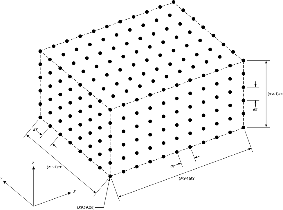
Fig. 4.62 Structured 3D grid for the low- or high-resolution domains.
NX_Low, NY_Low, and NZ_Low [integer] set the number of wind data points in each direction.
X0_Low, Y0_Low, and Z0_Low [m] set the origin of the grid (lowest-most X-Y-Z coordinate).
dX_Low, dY_Low, and dZ_Low [m] set the spatial discretization in each direction.
The total low-resolution domain size has dimensions (NX_Low-1)dX_Low \(\times\) (NY_Low-1)dY_Low \(\times\) (NZ_Low-1)dZ_Low. The low-resolution domain should extend throughout the wind farm wherever turbines and wakes may potentially reside with a resolution sufficient so that the spatial averaging is accurate, e.g., on the order of tens of meters for utility-scale wind turbines. Further guidance on choosing appropriate spatial discretization is given in Section 4.19.6.
Like the low-resolution domain, each high-resolution domain is stored as a structured 3D grid of wind data points in the global X-Y-Z inertial-frame coordinate system – as illustrated generically in Fig. 4.62.
NX_High, NY_High, and NZ_High [integer] set the number of wind data points in each direction. These values are the same for each wind turbine and so only need to be set once.
The origin and spatial discretization for the high-resolution wind domain for each turbine are specified in the Wind Turbines section of the FAST.Farm primary input file below.
InflowFile [quoted string] specifies the name of the primary input file for the InflowWind module, which can be specified relative to the location of the FAST.Farm primary input file or specified with an absolute path. It is recommended to use quotes around the file name. If there are spaces in the file or path names, these quotes are required. See Section 4.19.4.4 for information on the contents of this file.
4.19.4.2.5. Ambient Wind: Precursor in AMReX Format
The input parameters in this section are only used when Mod_AmbWind
= 4, indicating the use of ambient wind from a high-fidelity precursor
simulation stored in AMReX plot file
format. This option requires FAST.Farm to be compiled with the AMReX
library enabled (-DAMREX_READER=ON with CMake). The grid dimensions, origin,
and spatial discretization are read directly from the AMReX plot file
headers and do not need to be specified in the input file.
WindDirPrefix [quoted string] specifies the path prefix for the AMReX wind sub-volume directories. Sub-volume directories follow the naming convention <WindDirPrefix>_<sv>_<index>, where <sv> is the sub-volume number (0 for the low-resolution domain; 1 through NumTurbines for the high-resolution domain of each turbine) and <index> is a zero-padded integer directory index. The path can be specified relative to the location of the FAST.Farm primary input file or with an absolute path. It is recommended to use quotes around the path. See Section 4.19.4.5 for further details on the expected directory structure.
DirStartIndex [quoted string] specifies the directory index suffix
(e.g., "00000") corresponding to the simulation start time
\(t=0\). The string length determines the zero-padding width applied
to all directory index numbers; the number of leading zeros in
DirStartIndex sets the total field width used when constructing
subsequent directory names. FAST.Farm automatically searches for all
available time steps beginning from this index. It is recommended to use
quotes around this value.
DT_Low-AMReX [sec] sets the time step of the low-resolution ambient wind data and the global (driver/glue-code) time step of FAST.Farm. All FAST.Farm modules are called every DT_Low-AMReX seconds, although OpenFAST and its modules may use a time step that is an integer multiple smaller than or equal to DT_Low-AMReX. The value must match the time step used when generating the precursor simulation data.
DT_High-AMReX [sec] sets the time step of the high-resolution ambient wind data and must be an integer multiple smaller than or equal to DT_Low-AMReX. It must match the time resolution of the high-resolution sub-volumes in the precursor data. DT_Low-AMReX should be consistent with the timescales of wake dynamics (e.g., on the order of seconds), and DT_High-AMReX should be sufficient for accurate aerodynamic load calculations (e.g., on the order of fractions of a second). Further guidance is given in Section 4.19.6.
4.19.4.2.6. Wind Turbines
NumTurbines [integer] (\(N_t\)) is the number of wind turbines in the wind farm and determines the number of rows in the subsequent table (after two table header lines).
For each wind turbine:
WT_X, WT_Y, and WT_Z [m] specify the origin in the global X-Y-Z inertial-frame coordinate system. The origin is defined as the intersection of the undeflected tower centerline and the ground or, for offshore systems, mean sea level.
WT_FASTInFile [quoted string] specifies the name of the OpenFAST primary input file associated with each turbine. Each wind turbine is numbered within FAST.Farm as an integer (\(n_t\)) between 1 and NumTurbines corresponding to the row in the table. The OpenFAST primary input file name can be specified relative to the location of the FAST.Farm primary input file or with an absolute path. It is recommended to use quotes around the file name. Identical wind turbines can use the same OpenFAST primary input file, except if the corresponding OpenFAST model makes use of a Bladed-style controller in DLL format or, for offshore wind turbines, if different wave conditions are required for each turbine. If a Bladed-style DLL controller is being used, distinct Bladed-style controller DLLs must be used (each with a unique name). This requires the need for distinct ServoDyn primary input files, referencing the appropriate DLL name, and distinct OpenFAST primary input files, each referencing the appropriate ServoDyn primary input file name. If different wave conditions are required for each turbine, the distinct wave conditions (e.g., based on unique random wave seeds) for each wind turbine must be set in the HydroDyn primary input file and distinct OpenFAST primary input files must be used, each referencing the appropriate HydroDyn primary input file name. See Section 4.19.4.6 for information on the contents of the OpenFAST input files.
When Mod_AmbWind = 2 or 3, the Wind Turbines table has six additional columns to complete the spatial discretization of the high-resolution wind domain for each wind turbine:
X0_High, Y0_High, and Z0_High [m] set the origin of the grid.
dX_High, dY_High, dZ_High [m] set spatial discretization in each direction.
The total high-resolution domain size has dimensions (NX_High-1)dX_High \(\times\) (NY_High-1)dY_High \(\times\) (NZ_High-1)dZ_High. Each high-resolution domain must extend around the corresponding wind turbine, encompassing any turbine displacement. The domains should have a resolution sufficient for accurate aerodynamic load calculations, e.g., on the order of the blade chord length. The high-resolution domains will occupy the same space as portions of the low-resolution domain, requiring domains overlap.
4.19.4.2.7. Wake Dynamics
With FAST.Farm, each wake plane is treated as a radial finite-difference grid, as shown in Fig. 4.63.
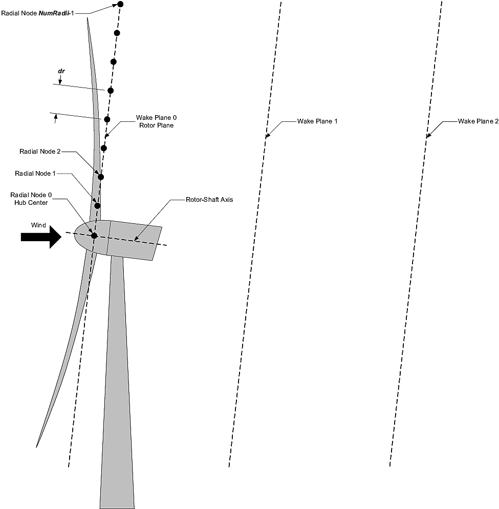
Fig. 4.63 Radial finite-difference grid. For clarity of the illustration, the number and size of the wake planes are shown smaller than they should be.
Three wake formulations are available (see Section 4.19.7 for more details):
Mod_Wake [switch] is used to switch between wake formulations. There are three options available: 1) Polar [Mod_Wake=1] (default); the wake is axi-symmetric, defined on a polar grid, solved using an implicit Crank-Nicolson scheme, satisfying both the momentum and mass conservation laws under a shear layer approximation. 2) Curled-wake model [Mod_Wake=2]; the wake is defined on a Cartesian grid, the effect of curled wake vorticies in skewed inflow is accounted for by introducing cross-flow velocities, the momentum conservation is solved using a first-order forward Euler scheme, mass conservation is not enforced, the effect of wake swirl may be accounted for. The wake will adopt a “curled” shape in skewed inflow. 3) Cartesian [Mod_Wake=3]; corresponds to model 2 with curled-wake vortices of zero intensities, leading to an axi-symmetric wake.
When Wake_Mod=2,3, the stability of the algorithm will depend on the choice of dr and DT_Low (see the guidelines (see the guidelines given in Section 4.19.6).
RotorDiamRef [float, in m]: Reference turbine rotor diameter for wake calculations.
The wake planes are defined by the following parameters:
dr [m] sets the radial increment. To ensure the wake deficits are accurately computed by FAST.Farm, dr should be set so that FAST.Farm sufficiently resolves the wake deficit within each plane. When a cartesian grid is used (Mod_Wake=2 or 2), dr represents the spacing in the y and z direction of the plane. When Wake_Mod=2,3, the stability of the algorithm will depend on the choice of dr and DT_Low (see the guidelines given in Section 4.19.6).
NumRadii [integer] (\(N_r\)) sets the number of radii. To ensure the wake deficits are accurately computed by FAST.Farm, NumRadii should be set so that the diameter of each wake plane, 2(NumRadii-1)dr, is large relative to the rotor diameter. When a Cartesian grid is used, the y and z coordinates extend from (-NumRaddi+1)*dr to (NumRadii-1)*dr.
NumPlanes [integer] (\(N_p\)) sets the number of wake planes. To ensure the wake deficits are accurately captured by FAST.Farm, NumPlanes should be set so that the wake planes propagate a sufficient distance downstream, preferably until the wake deficit decays away.
The next \(20\) inputs are user-specified calibration parameters and options that influence the wake-dynamics calculations. The parameters may depend, e.g., on turbine operation or atmospheric conditions that can be calibrated to better match experimental data or by using an HFM benchmark. Default values have been derived for each calibrated parameter based on SOWFA simulations ( [ff-Deal18]), but these can be overwritten by the user.
f_c [Hz] (\(f_c\)) is the cutoff (corner) frequency of the low-pass time filter for the wake advection, deflection, and meandering model and must be greater than zero. Preferably the filter constant should be set as follows:
where \(\tau_1\) is a time scale similar to the one used in the Oye dynamic inflow model and \(a_\text{avg}\) is the average axial induction factor across the rotor disk. If the DEFAULT keyword is specified in place of a numerical value, f_c is set to \(12.5/R_\text{est}\) Hz which corresponds to \(U=10\) m/s, \(a=1/3\) in the equation above, and where the estimated rotor radius is obtained as: \(R_\text{est} = (dr * NumRadii) / 3\). Changing the grid resolution will change the estimated radius, therefore it is recommended to set a numerical value for f_c directly instead of using DEFAULT. If numerical issues occur, you may attempt to lower the value of f_c to introduce more filtering of high frequencies. In previous release, the default value was excessively small, set to \(0.0007\) Hz.
C_HWkDfl_O [m] (\(C_{HWkDfl}^{O}\)) is the calibrated parameter for the wake deflection correction defining the horizontal offset at the rotor. If the DEFAULT keyword is specified in place of a numerical value, C_HWkDfl_O is set to \(0.0\).
C_HWkDfl_OY [m/deg] (\(C_{HWkDfl}^{OY}\)) is the calibrated parameter for the wake deflection correction defining the horizontal offset at the rotor scaled with yaw error. If the DEFAULT keyword is specified in place of a numerical value, C_HWkDfl_OY is set to \(0\) when Mod_Wake=2 C_HWkDfl_OY is set to \(0.3\) otherwise.
C_HWkDfl_x [-] (\(C_{HWkDfl}^{x}\)) is the calibrated parameter for the wake deflection correction defining the horizontal offset scaled with downstream distance. If the DEFAULT keyword is specified in place of a numerical value, C_HWkDfl_x is set to \(0.0\).
C_HWkDfl_xY [1/deg] (\(C_{HWkDfl}^{xY}\)) is the calibrated parameter for the wake deflection correction defining the horizontal offset scaled with downstream distance and yaw error. If the DEFAULT keyword is specified in place of a numerical value, C_HWkDfl_xY is set to \(0.0\) when Mod_Wake=2. C_HWkDfl_xY is set to \(-0.004\) otherwise.
C_NearWake (\(C_{NearWake}\)) [-] is the calibrated parameter for the near-wake correction and must be greater than one. If the DEFAULT keyword is specified in place of a numerical value, C_NearWake is set to \(1.8\).
k_vAmb [five floats, comma separated] \([k_{\nu Amb}, C_{\nu Amb}^{FMin}, C_{\nu Amb}^{DMin}, C_{\nu Amb}^{DMax}, C_{\nu Amb}^{Exp}]\) Tuning parameters for the ambient turbulence influence in the eddy viscosity. If the DEFAULT keyword is specified, all five parameters will be set to the default values specified below. The five parameters in order are:
- \(k_{\nu Amb}\) [-] (\(\gt 0\))
- \(C_{\nu Amb}^{FMin}\) [-] (\(\ge 0\), \(\le 1\))
- \(C_{\nu Amb}^{DMin}\) [-] (\(\ge 0\))
- \(C_{\nu Amb}^{DMax}\) [-] (\(\ge k_\text{DMin}\))
- \(C_{\nu Amb}^{Exp}\) [-] (\(\gt 0\))
k_vShr [five floats, comma separated] \([k_{\nu Shr}, C_{\nu Shr}^{FMin}, C_{\nu Shr}^{DMin}, C_{\nu Shr}^{DMax}, C_{\nu Shr}^{Exp}]\) Tuning parameters for the wake shear layer influence in the eddy viscosity. If the DEFAULT keyword is specified, all five parameters will be set to the default values specified below. The five parameters in order are:
- \(k_{\nu Shr}\) [-] (\(\gt 0\))
- \(C_{\nu Shr}^{FMin}\) [-] (\(\ge 0\), \(\le 1\))
- \(C_{\nu Shr}^{DMin}\) [-] (\(\ge 0\))
- \(C_{\nu Shr}^{DMax}\) [-] (\(\ge k_\text{DMin}\))
- \(C_{\nu Shr}^{Exp}\) [-] (\(\gt 0\))
Mod_WakeDiam [switch] specifies the wake diameter calculation model (method). There are four options: 1) use the rotor diameter [Mod_WakeDiam=1]; 2) use a velocity-based method [Mod_WakeDiam=2]; 3) use a mass-flux based method [Mod_WakeDiam=3]; or 4) use a momentum-flux based method [Mod_WakeDiam=4]. If the DEFAULT keyword is specified in place of a numerical value, Mod_WakeDiam is set to \(1\).
C_WakeDiam [-] (\(C_{WakeDiam}\)) is the calibrated parameter for the wake diameter calculation and must be greater than zero and less than \(0.99\). It is unused when Mod_WakeDiam=1. If the DEFAULT keyword is specified in place of a numerical value, C_WakeDiam is set to \(0.95\).
Mod_Meander [switch] specifies the spatial filter model (method) for wake meandering. There are three options: 1) use a uniform spatial average [Mod_Meander=1]; 2) use a truncated jinc [Mod_Meander=2]; or 3) use a windowed jinc [Mod_Meander=3]. If the DEFAULT keyword is specified in place of a numerical value, Mod_Meander is set to \(3\).
C_Meander [-] (\(C_{Meander}\)) is the calibrated parameter for the wake meandering and must be greater than or equal to one. If the DEFAULT keyword is specified in place of a numerical value, C_Meander is set to \(1.9\).
4.19.4.2.8. Curled wake parameters
Swirl [switch] Include swirl velocities in wake [only used if [Mod_Wake=2] or [Mod_Wake=3].
k_VortexDecay [-] This constant specifies the decay rate of the spanwise velocity components from the curled wake model. DEFAULT is 0.0.
NumVortices [-] The number of vortices in the curled wake model. DEFAULT is 100.
sigma_D [-] The width of the vortex core in the curled wake model non-dimesionalized by rotor diameter. If the DEFAULT keyword is specified in place of a numerical value, sigma_D is set to \(0.2\).
FilterInit [switch] The number of grid points (in the y and z directions) used to filter the initial wake plane deficit in the curled wake model. A value of zero corresponds to no filter. The filter is used to remove strong gradients in the wake, and stabilize the solution. DEFAULT is 1.
k_vCurl [-] Calibrated parameter for scaling the eddy viscosity in the curled-wake model. This value is a tuning parameters to increase or decrease the diffusion in the curled wake model. We have found that this value may be a function of the thrust coefficient, with higher values recommended for higher thrust coefficients. The following guidelines are suggested: \(k_v=0.9\) for \(C_T=0.4\), \(k_v=2.0\) for \(C_T=0.7\), \(k_v=3.0\) for \(C_T=0.9\). These guidelines may change in the future. The DEFAULT value is 2.0.
Mod_Projection [switch] Select how the wake plane velocity is projected in AWAE. There are two options: 1) keep all components 2) project against plane normal. If DEFAULT is used, then Mod_Projection=2 when Mod_Wake=2, and Mod_Projection=1 otherwise.
4.19.4.2.9. Wake-Added Turbulence (WAT)
The wake-added turbulence model is described in Section 4.19.7.2.3.4.
WAT [switch] Select whether the wake-added turbulence is included. There are three options: 0) no wake-added turbulence, 1) use predefined turbulence box for the background turbulence, 2) use a user defined turbulence box. When WAT=1, the number of points of the box are inferred from the filename, and the dimensions in each directions are taken as \(dx=dy=dz=0.03*\text{RotorDiamRef}\).
WAT_BoxFile: [quoted string] Filepath to the file containing the u-component of the turbulence box (either predefined or user-defined). This turbulence box is expected to be in the Mann box format. The filename should be of the form “Label_1024x32x16.u” where the extension “.u” is required. FAST.Farm will assume that files with extensions “.v” and “.w” are present, and these files will also be read. When WAT=1, the three digits separated by “x” in the filename are assumed to be the number of points in the x y and z dimension of the box.
WAT_NxNyNz: [three integers, comma separated] Number of points in the x, y, and z directions of the WAT_BoxFile. These are used only if WAT=2.
WAT_DxDyDz: [three floats, comma separated] Distances (in meters) between points in the x, y, and z directions of the WAT_BoxFile These are used only if WAT=2. When WAT=1 the dimensions will be set to [dX_high, dY_high, dZ_high] if that is the same for all turbines, otherwise the dimeinaiona will be calculated using the guidance with \(dx=dy=dz=0.03*\text{RotorDiamRef}\).
WAT_ScaleBox: [flag] When set to True, the input turbulence box is scaled so that it has zero mean and unit standard deviation at every node. DEFAULT is True.
WAT_k_Def [five floats, comma separated] \([k_\text{def}, k_\text{FMin}, k_\text{DMin}, k_\text{DMax}, e]\) Tuning parameters for quasi-steady wake deficit effect in the wake-added turbulence scaling factor. This tuning paramater is a function of the downstream position from the rotor using a set of five parameters. See equation (4.250) in section Section 4.19.7.2.3.4 (FAST.Farm theory) for details on the function used for WAT_k_Def. If the DEFAULT keyword is specified, all five parameters will be set to the default values specified below. The five parameters in order are:
- \(k_\text{def}\) [-] (\(\gt 0\))
- \(k_\text{FMin}\) [-] (\(\ge 0\), \(\le 1\))
- \(k_\text{DMin}\) [-] (\(\ge 0\))
- \(k_\text{DMax}\) [-] (\(\ge k_\text{DMin}\))
- \(e\) [-] (\(\gt 0\))
WAT_k_Grad [five floats, comma separated] \([k_\text{Grad}, k_\text{FMin}, k_\text{DMin}, k_\text{DMax}, e]\) Tuning parameters for gradient of the wake deficit in the wake-added turbulence scaling factor. This tuning paramater is a function of the downstream position from the rotor using a set of five parameters. See equation (4.250) in section Section 4.19.7.2.3.4 (FAST.Farm theory) for details on the function used for WAT_k_Grad. If the DEFAULT keyword is specified, all five parameters will be set to the default values specified below. The five parameters in order are:
- \(k_\text{grad}\) [-] (\(\gt 0\))
- \(k_\text{FMin}\) [-] (\(\ge 0\), \(\le 1\))
- \(k_\text{DMin}\) [-] (\(\ge 0\))
- \(k_\text{DMax}\) [-] (\(\ge k_\text{DMin}\))
- \(e\) [-] (\(\gt 0\))
4.19.4.2.10. Visualize
WrDisWind [flag] specifies whether full 3D low- and high-resolution disturbed wind data output files will be generated. These files show the ambient wind and wake interactions across the wind farm for visualization and are generated if WrDisWind=TRUE. The VTK data format and spatial resolutions (number of grid points, origin, and spacing) of these output files match those of the corresponding low- and high-resolution ambient wind data used by the FAST.Farm simulation. The VTK files are written to a directory named vtk_ff where the FAST.Farm primary file is stored. The naming conventions of these output files are <RootName>.Low.Dis.<nlow>.vtk and <RootName>.HighT<nt>*.Dis.<nt>.vtk for the low- and high-resolution disturbed wind data files, respectively, where <RootName> is the name of the FAST.Farm primary input file, excluding its file extension, where <nt> and <nlow> are as specified in Section 4.19.4.2.3, but include leading zeros.
For visualization, FAST.Farm can also output low-resolution disturbed (including wakes) wind data output files that are two-dimensional (2D) slices of the full low-resolution domain, specified by the following 7 inputs. Up to ninety-nine 2D slices parallel to the X-Y, Y-Z, and/or X-Z planes can be output.
NOutDisWindXY [integer] specifies the number of 2D slices parallel to the X-Y plane where low-resolution disturbed wind data output files are output (\(0\) to \(99\)).
OutDisWindZ [m] is a list NOutDisWindXY values long of the Z coordinates of each plane that will be output. These values are in the global inertial-frame coordinate system, separated by any combination of commas, semicolons, spaces, and/or tabs.
NOutDisWindYZ [integer] specifies the number of 2D slices parallel to the Y-Z plane where low-resolution disturbed wind data output files are output (\(0\) to \(99\)).
OutDisWindX [m] is a list NOutDisWindYZ values long of the X coordinates of each plane that will be output. These values are in the global inertial-frame coordinate system, separated by any combination of commas, semicolons, spaces, and/or tabs.
NOutDisWindXZ [integer] specifies the number of 2D slices parallel to the X-Z plane where low-resolution disturbed wind data output files are output (\(0\) to \(99\)).
OutDisWindY [m] is a list NOutDisWindXZ values long of the Y coordinates of each plane that will be output. These values are in the global inertial-frame coordinate system, separated by any combination of commas, semicolons, spaces, and/or tabs.
The VTK files are written to a directory named vtk_ff where the FAST.Farm primary file is stored. The naming conventions of these output files are <RootName>.Low.DisXY<nOut>.<nlow>.vtk, <RootName>.Low.DisYZ<nOut>.<nlow>.vtk, and <RootName>.Low.DisXZ<nOut>.<nlow>.vtk for the X-Y, Y-Z, and X-Z slices, respectively, where <nOut> is an integer between \(1\) and \(9\) corresponding to which slice is output. <RootName> and <nlow> are as defined in Section 4.19.4.2.3, but include leading zeros.
WrDisDT [sec] specifies the time step (inverse of the frame rate) of all disturbed wind data output files and must be an integer multiple larger than or equal to DT_Low. This input is unused when WrDisWind = FALSE and when NOutDisWindXY, NOutDisWindYZ, and NOutDisWindXZ are set to zero. If the DEFAULT keyword is specified in place of a numerical value, WrDisDT is set to DT_Low. Note that the full high-resolution disturbed wind data output files are not output at a frame rate of 1/DT_High, but are only output every WrDisDT seconds.
Visualizing the ambient wind and wake interactions can be useful for interpreting results and debugging problems. However, FAST.Farm will generate \(n+1\) files per output option when WrDisWind = TRUE and/or when NOutDisWindXY, NOutDisWindYZ, and/or NOutDisWindXZ are set greater than zero. This file generation will slow down FAST.Farm and take up a lot of disk space, especially when generating full low- and high-resolution disturbed wind data files. Therefore, disabling visualization is recommended when running many FAST.Farm simulations. See Section 4.19.5.3 for visualization output file details.
4.19.4.2.11. Output
SumPrint [flag] specifies if a summary file is generated. The file is generated if SumPrint=TRUE, with the name <RootName>.sum, where <RootName> is as defined above. See Section 4.19.5.2 for summary file details.
ChkptTime [sec] specifies how frequently checkpoint files are written for a potential restart, but is currently unused by FAST.Farm.
TStart [sec] specifies the simulation time at which FAST.Farm will begin writing data in the time-series results output file. Note that output files may not be generated at TStart seconds if TStart is not an integer multiple of DT_Low.
OutFileFmt [switch] specifies which type of time-series results output file will be generated. Three options are available, and are the same as those in OpenFAST: 1) generates an ASCII text file [OutFileFmt=1]; 2) generates a binary file [OutFileFmt=2]; or 3) generates both ASCII text and binary files [OutFileFmt=3]. However, FAST.Farm currently only supports text-based output files. Therefore, OutFileFmt must be set to 1.
TabDelim [flag] specifies how columns in the ASCII text output time-series results are delimited. If TabDelim = TRUE, the columns are tab-delimited. Otherwise, the columns are delimited with spaces. TabDelim is not used when OutFileFmt = 2.
OutFmt [string] specifies the ASCII text-based output file channel format (excluding the time channel). Values printed in the time-series results output file should result in a field that is 10 characters long; “ES10.3E2” is a common setting for OutFmt. The time channel is printed using the “F10.4” format. OutFmt is not used when OutFileFmt = 2. See Section 4.19.5.5 for details on time-series results files.
OutAllPlanes [-] Output all wake planes in VTK at all time steps. Note: this option requires intensive writing to disk and will drastically slow down the simulation. DEFAULT is False.
FAST.Farm can output wake-related quantities for up to 9 individual turbines, not considering the effects of wake merging, at up to 20 radial nodes and up to 9 downstream distances. These outputs are specified with the 4 following inputs:
NOutRadii [integer] specifies the number of radial nodes to be outputted (0 to 20).
OutRadii [integer] specifies the node numbers between 0 (at the wake center) and NumRadii-1 (at the outer extent of the radial finite-difference grid). Values are a list of length NOutRadii, separated by any combination of commas, semicolons, spaces, and/or tabs.
NOutDist [integer] specifies the number of downstream distances that output is requested for (0 to 9).
OutDist [m] specifies the downstream distances (not wake-plane numbers) and each must be greater or equal to zero. Values are a list of length NOutDist, separated by any combination of commas, semicolons, spaces, and/or tabs. The downstream distances are measured normal to the wake planes and an OutDist of zero corresponds to the rotor plane. Wake output quantities are linearly interpolated between wake planes. Only wake-related quantities for the first 9 turbines can be output and all wakes have the same output radial node numbers and downstream distances. The outputs specified in the OutList section determine which quantities are actually output at these output radial node numbers and downstream distances.
FAST.Farm can also output ambient wind velocities (not including wakes) and disturbed wind velocities (including wakes) at up to nine points (positions) in the low-resolution wind domain, defined with the following inputs:
NWindVel [integer] specifies the number of points where wind will be output (0 to 9).
WindVelX, WindVelY, and WindVelZ [m] specifies X, Y, Z and coordinates, respectively, in the global inertial-frame coordinate system. Values are lists of length NWindVel separated by any combination of commas, semicolons, spaces, and/or tabs. The outputs specified in the OutList section determine which wind velocities are actually output at these points.
OutList [quoted strings] controls output quantities generated by FAST.Farm. Enter one or more lines containing quoted strings that in turn contain one or more output parameter names. Separate output parameter names by any combination of commas, semicolons, spaces, and/or tabs. If you prefix a parameter name with a minus sign, “-”; underscore, “_”; or the characters “m” or “M”, FAST.Farm will multiply the value for that channel by \(-1\) before writing the data. The output columns are written in the order they are listed in the input file. FAST.Farm allows for the use of multiple lines so that lists can be broken into meaningful groups and so the lines can be shorter. Comments may be entered after the closing quote on any of the lines. Entering a line with the string “END” at the beginning of the line or at the beginning of a quoted string found at the beginning of the line will cause FAST.Farm to quit scanning for more lines of channel names. Wake-related output quantities are generated for the requested output radial node numbers and downstream distances through the OutRadii and OutDist lists above. Ambient and disturbed wind velocities are generated for the requested points through the WindVelX, WindVelY, and WindVelZ lists above. If FAST.Farm encounters an unknown/invalid channel name, it warns the users but will remove the suspect channel from the output file. Please refer to Section 4.19.12 for a complete list of possible output parameters.
4.19.4.3. Ambient Wind Precursor Files in Visualization Toolkit Format
When using ambient wind generated by a high-fidelity precursor simulation with Mod_AmbWind = 1, ambient wind data files for both the low- and high-resolution domains must be pre-generated. Each of these ambient wind data files must follow the simple legacy serial VTK file format. A sample VTK-formatted file is given in Section 4.19.11.
FAST.Farm requires that the ambient wind data files be stored in specific subdirectories of the directory specified by WindFilePath and with specific file names. The low-resolution ambient wind data files must be stored in a subdirectory named Low and be named Amb.t<nlow>.vtk, where <nlow> is as specified in Section 4.19.4.2.3. The high-resolution ambient wind data files must be stored in a subdirectory named HighT<nt> and be named Amb.t<nhigh>.vtk, where <nt> and <nhigh> are as specified in Section 4.19.4.2.3. Subdirectory HighT<nt> should contain the high-resolution ambient wind data corresponding to wind turbine nt specified in the Wind Turbines section of the FAST.Farm primary input file – see Section 4.19.4.2.6.
Each VTK-formatted input file begins with a file version and identifier, but is not checked by FAST.Farm. The second line is the header information that is for identifying specific cases, but is not used by FAST.Farm. The third line must include the single word ASCII, designating the file format currently supported by FAST.Farm.
The fourth line must contain the words DATASET STRUCTURED_POINTS, designating the data set structure currently supported by FAST.Farm. The next three lines set the spatial discretization of the domain. Each domain is stored as a structured 3D grid of wind data points (representing the corners of 3D cells) in the global X-Y-Z inertial-frame coordinate system – as illustrated generically in Fig. 4.62. The number of wind data points in each direction are set by DIMENSIONS followed by three integers separated by white space representing NX, NY, and NZ; the origin of the grid (lowest-most X-Y-Z coordinate) is set by ORIGIN followed by three floating real numbers separated by white space representing X0, Y0, and Z0; and the spatial discretization in each direction are set by SPACING followed by three floating real numbers separated by white space representing dX, dY, and dZ. The total domain size has dimensions (NX-1)dX \(\times\) (NY-1)dY \(\times\) (NZ-1)dZ.
The eighth line must contain the word POINT_DATA followed by an integer number specifying the number of wind data points, i.e., NX \(\times\) NY \(\times\) NZ. The ninth line must contain the word VECTORS followed by the data name (not used by FAST.Farm) and FLOAT, which defines the format of the data stored on the grid. Alternatively, the ninth line must contain the word FIELD followed by the data name (not used by FAST.Farm) and 1 and the tenth line must contain the array name (not used by FAST.Farm) followed by 3, the number of wind data points, i.e., NX \(\times\) NY \(\times\) NZ, and FLOAT. The remaining NX \(\times\) NY \(\times\) NZ lines of the file contain the X-Y-Z components of the ambient wind velocity at each wind data point stored as three floating real numbers separated by white space. The first data point corresponds to the ORIGIN and the remaining points involve looping through X, then Y, and then Z. For a ground or wave surface that is not flat and level – e.g., complex terrain or time-varying sea-surface elevation for offshore systems – the wind velocity components at a given wind data point should be written as NaN (not a number) 1 if that point is below the surface (not exposed to the atmosphere).
4.19.4.4. Ambient Wind with InflowWind Module Input Files
When using ambient wind through the interface to the InflowWind module with Mod_AmbWind = 2 or 3, the ambient wind is specified within standard InflowWind input files described in the OpenFAST documentation. The name of the primary InflowWind input file is specified by input parameter InflowFile in FAST.Farm. Please note that InflowFile is independent of the InflowWind primary input file used by the OpenFAST model of each wind turbine.
The InflowWind primary input file is processed the same when running FAST.Farm simulations as it would when running simulations in stand-alone OpenFAST. The only difference is that input parameter OutList in the InflowWind primary input file is ignored and replaced with equivalent output settings in FAST.Farm. All wind file type options and their associated input options are supported by FAST.Farm. Wind file type options are specified with input parameter WindType in the InflowWind primary input file. The available input options include steady wind, uniform time-varying wind, e.g., discrete gusts, and, full-field turbulent wind (in TurbSim, Bladed, and HAWC formats).
The wind data specified within InflowWind must encompass the entire low- and high-resolution domains defined within FAST.Farm for the entire simulation. This is because the ambient wind data specified within InflowWind will be interpolated to low- and high-resolution domains for use within FAST.Farm. To ensure this when using full-field turbulent wind data in InflowWind, it is recommend that:
The full-field wind data files be generated periodically so that the wind domain in InflowWind effectively extends forever along the wind propagation direction.
The input parameter PropagationDir in the InflowWind primary input file be set to \(0\), \(\pm90\), or \(180\) degrees so that the wind propagates along the \(\pm X\) or \(\pm Y\) axes of the FAST.Farm inertial-frame coordinate system (the exact direction should depend on the orientation of the wind turbines and farm).
When using full-field turbulent wind data in InflowWind, it is recommended that the 2D grid where the full-field turbulent wind data are defined be coincident with either the Y-Z grid of the high-resolution domain when PropogationDir = \(0\) or \(180\) degrees or the X-Z grid of the high-resolution domain when PropogationDir = \(\pm90\) degrees for each wind turbine. This is done to avoid doubly interpolating the wind data (once by FAST.Farm when generating the high-resolution domain and once by OpenFAST when accessing high-resolution wind at turbine analysis nodes).
When using ambient wind through multiple instances of the InflowWind module, i.e, when Mod_AmbWind = 3, only one InflowWind input file is specified. However, multiple wind data files are used, each with a different name. Specifically, the file name in the InflowWind input file in this case specifically refers only to the directory path of the wind files. The wind file root names are required to be Low for the low-resolution domain and HighT<nt> for the high-resolution domain associated with turbine \(n_\text{t}\). 2 Setting Mod_AmbWind to 2 or 3 has no influence when steady inflow is used (WindType = 1). When using full-field turbulent wind data in InflowWind with Mod_AmbWind = 3, it is required that:
The full-field wind data files be generated periodically. This effectively extends the wind domain forever along the wind propagation direction.
The input parameter PropagationDir in the InflowWind input file be set to \(0\) degrees so that the wind propagates along the X axis of the FAST.Farm inertial-frame coordinate system.
The wind data files associated with the high-resolution ambient wind be spatially and temporally synchronized with the low-resolution wind data file. The spatial synchronization must be based on the global X-Y-Z offsets of each turbine origin relative to the origin of the inertial frame coordinate system.
4.19.4.5. Ambient Wind Precursor Files in AMReX Plot File Format
When using Mod_AmbWind = 4, the ambient wind data must be
pre-generated and stored as AMReX plot files. AMReX plot files are
directories containing a Header file and one or more cell-data files
storing three-component (X, Y, Z) velocity fields on a structured
Cartesian grid. FAST.Farm reads the grid dimensions, origin, and
spacing from the Header and requires exactly three velocity
components (x_velocity, y_velocity, z_velocity or equivalent
names in order).
The sub-volume directories must follow the naming convention <WindDirPrefix>_<sv>_<index>, where:
WindDirPrefix is the path prefix specified in the FAST.Farm primary input file.
<sv> is the sub-volume number:
0for the low-resolution domain and1through NumTurbines for the high-resolution domain of each wind turbine.<index> is a zero-padded integer index with the same field width as DirStartIndex. The index for time step \(n\) is \(\text{DirStartNum} + n \times \Delta_\text{index}\), where \(\text{DirStartNum}\) is the integer value of DirStartIndex and \(\Delta_\text{index}\) is the stride between successive directory indices (determined automatically by FAST.Farm by scanning the available directories).
During initialization, FAST.Farm reads the header of the starting sub-volume for each domain (low-resolution sub-volume 0 and each high-resolution sub-volume 1 through NumTurbines) to obtain the grid properties, then calls the directory-discovery routine to confirm that a sufficient number of time steps exist and that the grid properties are consistent across all time steps. Specifically, FAST.Farm verifies:
That at least NumDT low-resolution and high-resolution directories are available for the simulation duration.
That the grid dimensions, origin, and spacing are identical across all time steps for a given sub-volume.
That the grid dimensions are the same for all high-resolution sub-volumes (one per turbine).
Because the grid properties are determined from the precursor data files, the user does not specify low- or high-resolution grid dimensions or origins in the FAST.Farm primary input file when using Mod_AmbWind = 4. The Wind Turbines table also requires only the standard four columns (WT_X, WT_Y, WT_Z, WT_FASTInFile), without the six additional high-resolution grid columns that are needed for Mod_AmbWind = 2 or 3.
Note
AMReX support is only available when compiling with CMake and must be enabled at
compile time by passing -DAMREX_READER=ON during configuration. If FAST.Farm
is compiled without AMReX support, setting Mod_AmbWind = 4 will
produce a fatal error.
4.19.4.6. OpenFAST Input Files
In addition to the FAST.Farm-specific input files, the OpenFAST model of each wind turbine also requires input files.
WT_FASTInFile [quoted string] specifies the OpenFAST primary input file for each wind turbine, including path. This is required in addition to the FAST.Farm-specific input files. The OpenFAST primary file, in turn, identifies several module-level input files. These OpenFAST input files are described in the OpenFAST documentation. Identical wind turbines can use the same OpenFAST primary input file, except if the corresponding OpenFAST model makes use of a Bladed-style controller in DLL format or, for offshore wind turbines, if different wave conditions are required for each turbine. If a Bladed-style DLL controller is being used, distinct Bladed-style controller DLLs must be used (each with a unique name). This requires the need for distinct ServoDyn primary input files, referencing the appropriate DLL name, and distinct OpenFAST primary input files, each referencing the appropriate ServoDyn primary input file name. If different wave conditions are required for each turbine, the distinct wave conditions (e.g., based on unique random wave seeds) for each wind turbine must be set in the HydroDyn primary input file and distinct OpenFAST primary input files must be used, each referencing the appropriate HydroDyn primary input file name.
Please note that the following input parameters in OpenFAST are interpreted differently when running FAST.Farm simulations than when running simulations in stand-alone OpenFAST.
AbortLevel in the OpenFAST primary input file is ignored and replaced with the equivalent input set in the FAST.Farm primary input.
TMax in the OpenFAST primary input file is ignored and replaced with the equivalent input set in the FAST.Farm primary input.
CompInflow in the OpenFAST primary input file must be set to 1 (to use the InflowWind module).
CompAero in the OpenFAST primary input file must be set to 2 (to use the AeroDyn v15 module).
WindType and its associated input parameters in the OpenFAST InflowWind module primary input file are ignored and replaced with the disturbed wind (including wakes) computed across the high-resolution domain for each wind turbine.
PropogationDir in the OpenFAST InflowWind module primary input file is ignored.
PCMode, VSContrl, HSSBRMode, and YCMode in the OpenFAST ServoDyn module primary input file must not be set to 4 because the Simulink/Labview interface is not currently supported by FAST.Farm.
All input parameters across the various OpenFAST input files pertaining to the wind turbine geometry defined relative to the origin of the OpenFAST inertial-frame coordinate system remain unchanged. Turbine origins are defined as the intersection of the undeflected tower centerline and the ground or, for offshore systems, mean sea level. Note, however, this origin ((\(0\),\(0\),\(0\)) in the OpenFAST inertial-frame coordinate system) is located at (WT_X,WT_Y,WT_Z) in the FAST.Farm global X-Y-Z inertial-frame coordinate system.