4.15.2. Extended Bladed Interface
The Bladed style DLL controller interface was extended to allow for a significant number of new channels arranged in channel groups in reserved ranges. This is shown in Fig. 4.53 below.
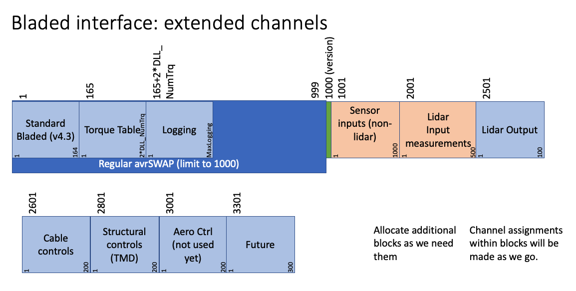
Fig. 4.53 Channel scheme for extension to the Bladed DLL interface.
The ServoDyn summary file contains a summary of all DLL inteface channels in use, as well as blocks of channels that are reserved.
  Legacy Bladed DLL interface channel usage by SrvD:

                 -->   indicates from SrvD to DLL
                 <--   indicates from DLL to SrvD
                 <->   indicates from bidirectional
      Record #         Description
      --------         -----------
           1      -->  Status flag set as follows: 0 if this is the first call, 1 for all subsequent time steps, -1 if this is the final call at the end of the simulation (-)
           2      -->  Current time (sec) [t in single precision]
           3      -->  Communication interval (sec)
           4      -->  Blade 1 pitch angle (rad) [SrvD input]
           5      -->  Below-rated pitch angle set-point (rad) [SrvD Ptch_SetPnt parameter]
           6      -->  Minimum pitch angle (rad) [SrvD Ptch_Min parameter]
           7      -->  Maximum pitch angle (rad) [SrvD Ptch_Max parameter]
           8      -->  Minimum pitch rate (most negative value allowed) (rad/s) [SrvD PtchRate_Min parameter]
           9      -->  Maximum pitch rate                               (rad/s) [SrvD PtchRate_Max parameter]
          10      -->  0 = pitch position actuator, 1 = pitch rate actuator (-) [must be 0 for ServoDyn]
          11      -->  Current demanded pitch angle (rad) [I am sending the previous value for blade 1 from the DLL, in the absence of any more information provided in Bladed documentation]
          12      -->  Current demanded pitch rate  (rad/s) [always zero for ServoDyn]
          13      -->  Demanded power (W) [SrvD GenPwr_Dem parameter from input file]
          14      -->  Measured shaft power (W) [SrvD input]
          15      -->  Measured electrical power output (W) [SrvD calculation from previous step; should technically be a state]
          16      -->  Optimal mode gain (Nm/(rad/s)^2) [if torque-speed table look-up not selected in input file, use SrvD Gain_OM parameter, otherwise use 0 (already overwritten in Init routine)]
          17      -->  Minimum generator speed (rad/s) [SrvD GenSpd_MinOM parameter]
          18      -->  Optimal mode maximum speed (rad/s) [SrvD GenSpd_MaxOMp arameter]
          19      -->  Demanded generator speed above rated (rad/s) [SrvD GenSpd_Dem parameter]
          20      -->  Measured generator speed (rad/s) [SrvD input]
          21      -->  Measured rotor speed (rad/s) [SrvD input]
          22      -->  Demanded generator torque above rated (Nm) [SrvD GenTrq_Dem parameter from input file]
          23      -->  Measured generator torque (Nm) [SrvD calculation from previous step; should technically be a state]
          24      -->  Measured yaw error (rad) [SrvD input]
          25      -->  Start of below-rated torque-speed look-up table (Lookup table not in use)
          26      -->  No. of points in torque-speed look-up table (-) [SrvD DLL_NumTrq parameter]:
          27      -->  Hub wind speed (m/s) [SrvD input]
          28      -->  Pitch control: 0 = collective, 1 = individual (-) [SrvD Ptch_Cntrl parameter]
          29      -->  Yaw control: 0 = yaw rate control, 1 = yaw torque control (-) [must be 0 for ServoDyn]
          30      -->  Blade 1 root out-of-plane bending moment (Nm) [SrvD input]
          31      -->  Blade 2 root out-of-plane bending moment (Nm) [SrvD input]
          32      -->  Blade 3 root out-of-plane bending moment (Nm) [SrvD input]
          33      -->  Blade 2 pitch angle (rad) [SrvD input]
          34      -->  Blade 3 pitch angle (rad) [SrvD input]
          35      <--  Generator contactor (-) [sent to DLL at the next call]
          36      <->  Shaft brake status (-) [sent to DLL at the next call; anything other than 0 or 1 is an error]
          37      -->  Nacelle yaw angle from North (rad)
          41      <--  demanded yaw actuator torque [this output is ignored since record 29 is set to 0 by ServoDyn indicating yaw rate control]
          45      <--  Demanded pitch angle (Collective pitch) (rad)
          47      <--  Demanded generator torque (Nm)
          48      <--  Demanded nacelle yaw rate (rad/s)
          49      -->  Maximum number of characters in the "MESSAGE" argument (-) [size of ErrMsg argument plus 1 (we add one for the C NULL CHARACTER)]
          50      -->  Number of characters in the "INFILE"  argument (-) [trimmed length of DLL_InFile parameter plus 1 (we add one for the C NULL CHARACTER)]
          51      -->  Number of characters in the "OUTNAME" argument (-) [trimmed length of RootName parameter plus 1 (we add one for the C NULL CHARACTER)]
          53      -->  Tower top fore-aft     acceleration (m/s^2) [SrvD input]
          54      -->  Tower top side-to-side acceleration (m/s^2) [SrvD input]
          55      <--  UNUSED: Pitch override [anything other than 0 is an error in ServoDyn]
          56      <--  UNUSED: Torque override [anything other than 0 is an error in ServoDyn]
          60      -->  Rotor azimuth angle (rad) [SrvD input]
          61      -->  Number of blades (-) [SrvD NumBl parameter]
          62      -->  Maximum number of values which can be returned for logging (-) [set to 300]
          63      -->  Record number for start of logging output (-) [set to ###]
          64      -->  Maximum number of characters which can be returned in "OUTNAME" (-) [set to 12601 (including the C NULL CHARACTER)]
          65      <--  Number of variables returned for logging [anything greater than MaxLoggingChannels is an error]
          69      -->  Blade 1 root in-plane bending moment (Nm) [SrvD input]
          70      -->  Blade 2 root in-plane bending moment (Nm) [SrvD input]
          71      -->  Blade 3 root in-plane bending moment (Nm) [SrvD input]
          73      -->  Rotating hub My (GL co-ords) (Nm) [SrvD input]
          74      -->  Rotating hub Mz (GL co-ords) (Nm) [SrvD input]
          75      -->  Fixed    hub My (GL co-ords) (Nm) [SrvD input]
          76      -->  Fixed    hub Mz (GL co-ords) (Nm) [SrvD input]
          77      -->  Yaw bearing  My (GL co-ords) (Nm) [SrvD input]
          78      -->  Yaw bearing  Mz (GL co-ords) (Nm) [SrvD input]
          82      -->  Nacelle roll    acceleration (rad/s^2) [SrvD input] -- this is in the shaft (tilted) coordinate system, instead of the nacelle (nontilted) coordinate system
          83      -->  Nacelle nodding acceleration (rad/s^2) [SrvD input]
          84      -->  Nacelle yaw     acceleration (rad/s^2) [SrvD input] -- this is in the shaft (tilted) coordinate system, instead of the nacelle (nontilted) coordinate system
          95      -->  Reserved (SrvD customization: set to SrvD AirDens parameter)
          96      -->  Reserved (SrvD customization: set to SrvD AvgWindSpeed parameter)
         109      -->  Shaft torque (=hub Mx for clockwise rotor) (Nm) [SrvD input]
         110      -->  Thrust - Rotating low-speed shaft force x (GL co-ords) (N) [SrvD input]
         111      -->  Nonrotating low-speed shaft force y (GL co-ords) (N) [SrvD input]
         112      -->  Nonrotating low-speed shaft force z (GL co-ords) (N) [SrvD input]
         117      -->  Controller state [always set to 0]
         120      <--  Airfoil command, blade 1
         121      <--  Airfoil command, blade 2
         122      <--  Airfoil command, blade 3
         129      -->  Maximum extent of the avrSWAP array: 3300

   Legacy Bladed DLL interface with Extended avrSWAP
          channel usage by SrvD:

                 -->   indicates from SrvD to DLL
                 <--   indicates from DLL to SrvD
      Record #         Requested by            Description
      --------         ---------------------   -----------
        1000     -->                           Version of extended avrSWAP: 1
        1001     -->                           General channel group -- Platform motion -- Displacement TDX (m)
        1002     -->                           General channel group -- Platform motion -- Displacement TDY (m)
        1003     -->                           General channel group -- Platform motion -- Displacement TDZ (m)
        1004     -->                           General channel group -- Platform motion -- Displacement RDX (rad)
        1005     -->                           General channel group -- Platform motion -- Displacement RDY (rad)
        1006     -->                           General channel group -- Platform motion -- Displacement RDZ (rad)
        1007     -->                           General channel group -- Platform motion -- Velocity     TVX (m/s)
        1008     -->                           General channel group -- Platform motion -- Velocity     TVY (m/s)
        1009     -->                           General channel group -- Platform motion -- Velocity     TVZ (m/s)
        1010     -->                           General channel group -- Platform motion -- Velocity     RVX (rad/s)
        1011     -->                           General channel group -- Platform motion -- Velocity     RVY (rad/s)
        1012     -->                           General channel group -- Platform motion -- Velocity     RVZ (rad/s)
        1013     -->                           General channel group -- Platform motion -- Acceleration TAX (m/s^2)
        1014     -->                           General channel group -- Platform motion -- Acceleration TAY (m/s^2)
        1015     -->                           General channel group -- Platform motion -- Acceleration TAZ (m/s^2)
        1016     -->                           General channel group -- Platform motion -- Acceleration RAX (rad/s^2)
        1017     -->                           General channel group -- Platform motion -- Acceleration RAY (rad/s^2)
        1018     -->                           General channel group -- Platform motion -- Acceleration RAZ (rad/s^2)
        2000     -->                           Ending   index for the non-lidar measurements channel block
        2001     -->                           Starting index for the lidar measurements channel block
        2500     -->                           Ending   index for the lidar measurements channel block
        2501     <--                           Starting index for the lidar control channel block
        2600     <--                           Ending   index for the lidar control channel block
        2601     <--    MoorDyn                Cable control channel group 1 -- DeltaL
        2602     <--    MoorDyn                Cable control channel group 1 -- DeltaLdot
        2603     <--                           Cable control channel group 2 -- DeltaL
        2604     <--                           Cable control channel group 2 -- DeltaLdot
        2605     <--    MoorDyn                Cable control channel group 3 -- DeltaL
        2606     <--    MoorDyn                Cable control channel group 3 -- DeltaLdot
        2800     <--                           Ending   index for the cable control channel block
        2801     -->                           StC control channel group 1 -- StC_Disp_X
        2802     -->                           StC control channel group 1 -- StC_Disp_Y
        2803     -->                           StC control channel group 1 -- StC_Disp_Z
        2804     -->                           StC control channel group 1 -- StC_Vel_X
        2805     -->                           StC control channel group 1 -- StC_Vel_Y
        2806     -->                           StC control channel group 1 -- StC_Vel_Z
        2807     <--                           StC control channel group 1 -- StC_Stiff_X (override spring  constant)
        2808     <--                           StC control channel group 1 -- StC_Stiff_Y (override spring  constant)
        2809     <--                           StC control channel group 1 -- StC_Stiff_Z (override spring  constant)
        2810     <--                           StC control channel group 1 -- StC_Damp_X  (override damping constant)
        2811     <--                           StC control channel group 1 -- StC_Damp_Y  (override damping constant)
        2812     <--                           StC control channel group 1 -- StC_Damp_Z  (override damping constant)
        2813     <--                           StC control channel group 1 -- StC_Brake_X (braking force)
        2814     <--                           StC control channel group 1 -- StC_Brake_Y (braking force)
        2815     <--                           StC control channel group 1 -- StC_Brake_Z (braking force)
        2816     <--                           StC control channel group 1 -- StC_Force_X (additional force)
        2817     <--                           StC control channel group 1 -- StC_Force_Y (additional force)
        2818     <--                           StC control channel group 1 -- StC_Force_Z (additional force)
        2819     <--                           StC control channel group 1 -- Reserved for future
        2820     <--                           StC control channel group 1 -- Reserved for future
        2821     -->    SStC2                  StC control channel group 2 -- StC_Disp_X
        2822     -->    SStC2                  StC control channel group 2 -- StC_Disp_Y
        2823     -->    SStC2                  StC control channel group 2 -- StC_Disp_Z
        2824     -->    SStC2                  StC control channel group 2 -- StC_Vel_X
        2825     -->    SStC2                  StC control channel group 2 -- StC_Vel_Y
        2826     -->    SStC2                  StC control channel group 2 -- StC_Vel_Z
        2827     <--    SStC2                  StC control channel group 2 -- StC_Stiff_X (override spring  constant)
        2828     <--    SStC2                  StC control channel group 2 -- StC_Stiff_Y (override spring  constant)
        2829     <--    SStC2                  StC control channel group 2 -- StC_Stiff_Z (override spring  constant)
        2830     <--    SStC2                  StC control channel group 2 -- StC_Damp_X  (override damping constant)
        2831     <--    SStC2                  StC control channel group 2 -- StC_Damp_Y  (override damping constant)
        2832     <--    SStC2                  StC control channel group 2 -- StC_Damp_Z  (override damping constant)
        2833     <--    SStC2                  StC control channel group 2 -- StC_Brake_X (braking force)
        2834     <--    SStC2                  StC control channel group 2 -- StC_Brake_Y (braking force)
        2835     <--    SStC2                  StC control channel group 2 -- StC_Brake_Z (braking force)
        2836     <--    SStC2                  StC control channel group 2 -- StC_Force_X (additional force)
        2837     <--    SStC2                  StC control channel group 2 -- StC_Force_Y (additional force)
        2838     <--    SStC2                  StC control channel group 2 -- StC_Force_Z (additional force)
        2839     <--    SStC2                  StC control channel group 2 -- Reserved for future
        2840     <--    SStC2                  StC control channel group 2 -- Reserved for future
        3000     <--                           Ending   index for the StC control channel block