4.8.1. Introduction
SubDyn is a time-domain structural-dynamics module for multimember fixed-bottom substructures created by the National Laboratory of the Rockies (NLR) through U.S. Department of Energy Wind and Water Power Program support. The module has been coupled into the FAST aero-hydro-servo-elastic computer-aided engineering (CAE) tool. Substructure types supported by SubDyn include monopiles, tripods, jackets, and other non-floating lattice-type substructures common for offshore wind installations in shallow and transitional water depths. SubDyn can also be used to model lattice support structures for land-based wind turbines.
The new SubDyn module follows the requirements of the FAST modularization framework, couples to OpenFAST, and provides new capabilities (relative to prior released versions of the software) for modeling the dynamic loading on multimember substructures. (Refer to Appendix E and the changelog.txt file that is provided in the archives for more details about changes among different versions.) SubDyn can also be driven as a standalone code to compute the mode shapes, natural frequencies, and time-domain responses of substructures under prescribed motion at the interface to the tower, uncoupled from FAST and in the absence of external loading other than gravity.
SubDyn relies on two main engineering schematizations: (1) a linear frame finite-element beam model (LFEB), and (2) a dynamics system reduction via the Craig-Bampton(C-B) method, together with a static-improvement method (SIM), greatly reducing the number of modes needed to obtain an accurate solution. More details can be found in Section 6, and in [SDRJ13], [DS13], [DSRJ13], [JBH+20].
In SubDyn, the substructure is considered to be either clamped or supported by springs at the seabed, and rigidly connected to the transition piece (TP) at the substructure top nodes (interface nodes). The spring constants are provided by the user to simulate soil-structure-interaction (SSI). Other restraint formulations may be implemented in the future. Only the substructure structural dynamics are intended to be modeled within SubDyn. When integrated with FAST, the structural dynamics of the TP, tower, and rotor-nacelle assembly (RNA) are modeled within FAST’s ElastoDyn module and hydrodynamics are modeled within FAST’s HydroDyn module. For full lattice support structures or other structures with no transition piece, however, the entire support structure up to the yaw bearing may be modeled within SubDyn. Modeling the tower in SubDyn as opposed to ElastoDyn, for example, allows for the possibility of including more than the first two fore-aft and side-to-side bending modes, thus accounting for more general flexibility of the tower and its segments. However, for tubular towers, the structural model in ElastoDyn tends to be more accurate because ElastoDyn considers geometric nonlinearities not treated in SubDyn.
Loads and responses are transferred between SubDyn, HydroDyn, and ElastoDyn via the FAST driver program (glue code) to enable hydro-elastic interaction at each coupling time step. At the interface nodes, the TP six degree-of-freedom (DOF) displacements (three translations and three rotations), velocities, and accelerations are inputs to SubDyn from ElastoDyn; and the six reaction loads at the TP (three forces and three moments) are outputs from SubDyn to ElastoDyn. SubDyn also outputs the local substructure displacements, velocities, and accelerations to HydroDyn in order to calculate the local hydrodynamic loads that become inputs for SubDyn. In addition, SubDyn can calculate member internal reaction loads, as requested by the user (see Figure 1).
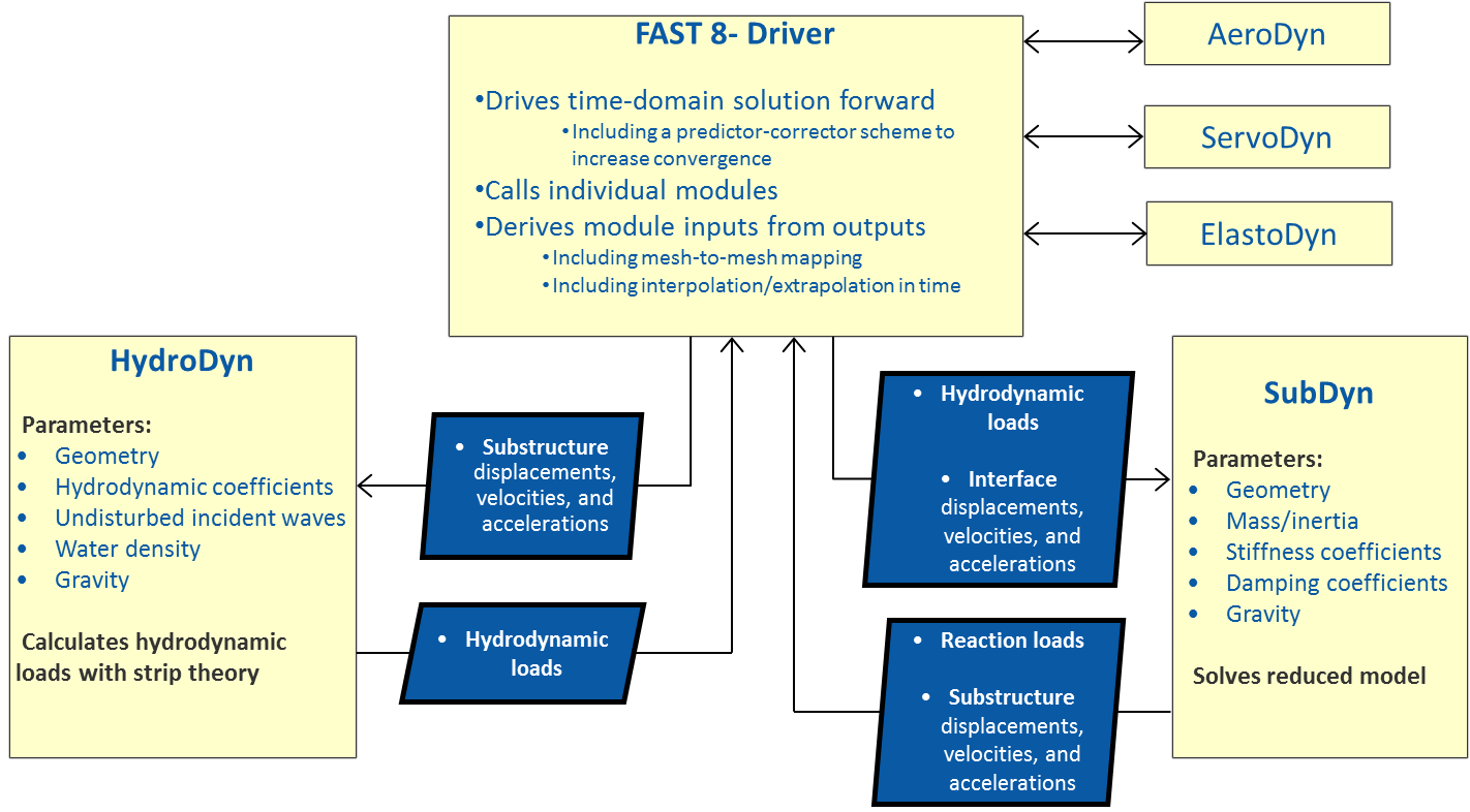
Fig. 4.37 SubDyn, HydroDyn, and FAST 8 coupled interaction
The input file defines the substructure geometry, material properties, restraints and SSI data files, finite-element resolution, number of retained modes in the dynamics system reduction, modal damping coefficients, and auxiliary parameters. The geometry is defined by joint coordinates in the global reference system (inertial-frame coordinate system shown in ), with the origin at the intersection of the undeflected tower centerline with mean sea level (MSL) or ground level for land-based structures. A member connects two joints; multiple members may use a common joint. Nodes are the result of the member refinement into multiple (*NDiv* input parameter) elements (nodes are located at the ends of each element, as shown in ), and they are calculated by the module.
In the current release, the geometry of a member is defined by its outer diameter and wall thickness (assuming a tubular geometry), and the material properties are defined by its Young’s modulus, shear modulus, and mass density. Member properties are specified at the joints; if properties change from one joint to the other, they will be linearly interpolated for the inner elements. Thus, a tapered member will be treated as a cylindrical member with step-wise variation of its properties. In a future release, a tapered finite-element formulation will be implemented, and a more accurate representation of a tapered member will become available.
The hydrodynamic loads (including buoyancy) are computed by HydroDyn and transferred by the glue code at those nodes that are underwater (submerged nodes). Additionally, the self-weight distributed load components (from gravity) are calculated by SubDyn and applied at all the nodes. Note that other load and inertial properties may be input via the HydroDyn module input file, where marine growth and flooding/ballasting of the members can be specified.
This document is organized as follows. Section Running SubDyn details how to obtain the SubDyn and FAST software archives and run either the stand-alone version of SubDyn or SubDyn coupled to FAST. Section Input Files describes the SubDyn input files. Section 4 discusses the Output Files generated by SubDyn; these include echo files, a summary file, and the results file. Section 5 provides modeling guidance when using SubDyn. The SubDyn theory is covered in Section SubDyn Theory. Section Known Limitations and Future Work outlines future work, and Section 8 contains a list of references. Example input files are shown in Appendices Section 4.8.9 and B. A summary of available output channels are found in Appendix Appendix D. List of Output Channels. Instructions for compiling the stand-alone SubDyn program are detailed in Appendix D. Appendix E tracks the major changes that have been made to SubDyn for each public release.