4.13.1. InflowWind Driver
Example input files are included in Section 4.13.6.
Command-line syntax for InflowWind driver:
InflowWind_Driver <filename> [options]

      where:  <filename>     --   Name of driver input file to use
    options:  /ifw           --   treat <filename> as name of InflowWind input file (no driver input file)

    The following options will override values in the driver input file:
              /DT[#]          --  timestep
              /TStart[#]      --  start time
              /TSteps[#]      --  number of timesteps
              /xrange[#:#]    --  range of x (#'s are reals)
              /yrange[#:#]    --  range of y
              /zrange[#:#]    --  range in z (ground = 0.0)
              /Dx[#]          --  spacing in x
              /Dy[#]          --  spacing in y
              /Dz[#]          --  spacing in z
              /points[FILE]   --  calculates at x,y,z coordinates specified in a white space delimited FILE
              /v              --  verbose output
              /vv             --  very verbose output
              /hawc           --  convert wind file specified in InflowWind to HAWC format
              /bladed         --  convert wind file specified in InflowWind to Bladed format
              /vtk            --  convert wind file specified in InflowWind to VTK format
              /accel          --  output acceleration when processing a points file
              /BoxExceedAllow --  set flag to extrapolate values of points outside FF wind box
              /help           --  print this help menu and exit
Notes:
-   Unspecified ranges and resolutions default to what is in the file.
-   If no XRange is specified, assumed to be only at X=0
-   Options are not case sensitive.
The InflowWind Manual contains a description of file formats that it can read.
4.13.1.1. Specifying the InflowWind Input File
The InflowWind driver input file requires that an InflowWind input file be specified within it. See an example InflowWind input file in Section 4.13.6.
Within the InflowWind input file, if the wind file being specified is
Bladed native format (WindType = 7), please also see
Section 4.13.2.1.
4.13.1.2. Wind-file output formats
The InflowWind driver is capable of writing the wind data read from the input wind file into wind files of various formats.
4.13.1.2.1. HAWC2
This format generates the following files:
three binary files, one for each component:
<RootName>-HAWC.u,<RootName>-HAWC.v, and<RootName>-HAWC.wa text summary file in the style of HAWC2 input files:
<RootName>-HAWC.sum
In the conversion script, the u component will have the (approximate) mean removed at each height. The mean value that was removed is displayed as comments in the text summary file. The turbulence is not scaled, so it will have the same scaling as the original file.
4.13.1.2.2. Bladed
This format generates a packed binary file and a text summary file.
This output format is in the Bladed-style format that TurbSim generates. That means that the shear is included in the file.
4.13.1.2.3. VTK
This format creates files in a subdirectory called vtk. There is one
vtk file for each time in the full-field data structure, and the entire
Y-Z grid is printed in each file. This format can be used to visualize
the wind field using a viewer such as ParaView.
4.13.1.2.4. Uniform Wind
This format generates a text file in the uniform wind format. Converting to this format will generally lose information in the file because it specifies the wind speed and direction at only one point and approximates the shear as a power-law exponent.
4.13.1.3. Converting uniform wind to full-field wind format
When converting from a uniform wind file to a full-field wind format,
the following assumptions are used: - The advection speed is the
time-averaged horizontal wind speed in the uniform wind file (it does
not include the gust speed). - The constant time-step used in the output
file is the smallest difference between any two entries in the
hub-height file. - The maximum time in the uniform wind file will be
used as the maximum time in the FF binary file. - The grid is generated
with 5-m resolution in the lateral (Y) and horizontal (Z) directions. -
The size of the grid is based on the RefLength parameter in the
InflowWind input file. The converter adds approximately 10% to the grid
width, with the exact size determined by achieving the desired grid
resolution. The grid is centered in the lateral direction; it extends
vertically above RefHt by the same distance as the grid width, and
extends below RefHt to the ground (or within one grid point of the
ground).
Note that there is a potential time shift between the uniform and full-field wind files, equal to the time it takes to travel the distance of half the grid width. When using the resulting full-field files, care must be taken that the aeroelastic code does not treat it as periodic.
4.13.1.4. Converting from a full-field wind format to uniform wind format
When converting from a full-field wind format to a uniform wind file, the following assumptions are used:
The gust speed, horizontal shear, and vertical linear shear are all 0.
The Uniform Wind reference height is on a full-field grid point.
The upflow is calculated using the mean upflow value at the reference point.
The mean wind direction and upflow are removed from the reference grid point before writing the velocities to the Uniform Wind file.
The wind direction in the file is the sum of the mean wind direction and the instantaneous direction calculated between instantaneous U and V wind components.
The power law exponent is either
The power-law exponent specified in InflowWind (if a power law wind profile is used to add to the turbulence with native-Bladed or HAWC2 files), or
Calculated by using the mean wind speeds at two points: the reference (hub) height and the uppermost height on the grid.
4.13.1.5. accel flag
The ability to calculate the acceleration of the flow field was added to InflowWind to support the analysis of MHK, underwater, turbines. The acceleration is needed to calculate the fluid-inertia effects of the fluid interacting with the rotor. Calculation of the acceleration is supported for Uniform/Steady Wind and grid based wind profiles (Turbsim, HAWC, and Bladed files). Enabling this flag causes the driver to output the flow field acceleration for points defined in the Points file in addition to the velocities at those same points.
4.13.1.6. BoxExceedAllow flag
A feature was added to InflowWind to allow some requested points to lie outside the full field wind grid. This allows for a continuous exptrapolation of values beyond the grid that approaches an average level.
4.13.1.6.1. Purpose
When InflowWind is coupled to OpenFAST, wind points corresponding to the free vortex wake module (OLAF) in AeroDyn 15 and LidarSim module may be outside the full-field wind data. No other wind data points may be outside the grid (AeroDyn blades must be within the wind box). The wake from OLAF may over time stray outside the full-field wind box, in which case it should be sufficiently far from the turbine that any inacuracies in the reported wind value should have little to no effect on the turbine. The method employed here should allow the wake to continue evolving without flow reversals or other oddities due to a discontinuity at the wind grid boundary. However, to limit the impact of the approximation used, the wake should not be allowed to exit the box until far from the turbine.
The other use case is when the LidarSim requests data far from the turbine that may lie outside the wind box, such as a yawed, or floating turbine where the sensing beam periodically exits the wind box.
4.13.1.6.2. Method
During initialization, a flag and corresponding index are passed to tell IfW to allow points in the requested position array to lie outside the full-field wind and tower grids starting at this index. The values for these points are then extrapolated using the data from the full-field wind as follows:
The average wind value at each Z height at each timestep is calculated and stored during initialization (averaged across the Y dimension).
Wind above the full field wind grid is linearly interpolated between the value at the top of the grid the average of the top of the grid. This linear interpolation zone extends from the top of grid to the top of the grid + one half grid height (
FFZHWid). Values beyond that are held constant.Values beyond the +/-Y grid edges are linearly interpolated between the value at the edge of the grid and the average for that Z elevation in the grid. The interpolation zone is between the edge of the grid and one half grid width further along Y at
+/-2*FFYHWid.When no tower data is present, the values below the grid are linearly interpolated between the bottom of the grid and 0 at the ground.
When tower data is present, points below the grid are interpolated between the tower and grid and the ground (0 value at
+/-2*FFYHWid). Linear interpolation is then used beyond the edge of the grid.
4.13.1.6.3. Testing with driver
To test this feature, the driver accepts the flag BoxExceedAllow and will
signal to InflowWind that all windgrid points may be beyond the edge of the
grid. To use this, setup a driver input file with an output wind grid that is
larger than the full-field grid from the wind file referenced in the
corresponding InflowWind input file. Then the following command can be used
(Linux syntax, Windows is slightly different):
> inflowwind_driver -BoxExceedAllow MyDriverFile.inp
For a single YZ plane from the resulting wind grid output file at time T, the results for extrapolated data points can be plotted and should show characteristics similar to the following plots.
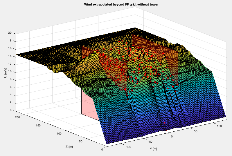
Fig. 4.51 Extrapolation of wind values beyond the full field wind grid when no tower data is present. The semi-transparent red planes indicate the edges of the full-field wind grid, and the red points are the locations of wind grid data in this example case. All other points shown on the surface are interpolated/extrapolated.
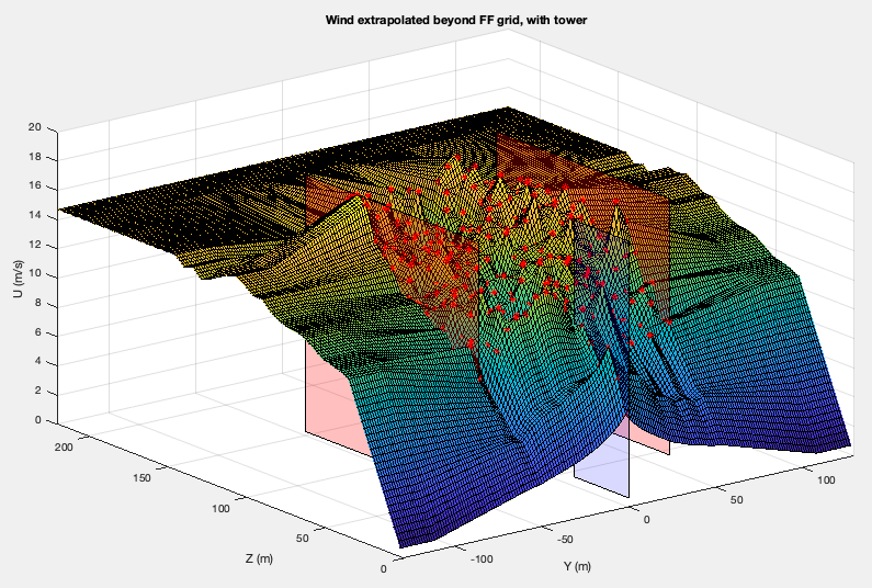
Fig. 4.52 Extrapolation of wind values beyond the full field wind grid when tower data is present. The semi-transparent red planes indicate the edges of th e full-field wind grid, blue semi-transparent plane indicates the tower grid, and the red points indcate the data points from the wind grid and tower. All other points shown on the surface are interpolated/extrapolated.