4.4.1. Introduction
Over the past few decades, substantial reductions in the cost of wind energy have come from large increases in rotor size. One important consideration for such large turbines is increased blade flexibility. In particular, large blade deflections may lead to a swept area that deviates significantly from the rotor plane. Such deviations violate assumptions used by common aerodynamic models, such as the blade element momentum (BEM) method. Such methods rely on actuator-disk assumptions that are only valid for axisymmetric rotor loads contained in a plane. Large blade deflections may also cause near wake of the turbine to diverge from a uniform helical shape. Further, interactions between turbine blades and the local near wake may increase, thus violating assumptions of models that do not account for the position and dynamics of the near wake. Additionally, highly flexible blades will likely cause increased unsteadiness and three-dimensionality of aerodynamic effects, increasing the importance of accurate and robust dynamic stall models. There are many other complex wind turbine situations that violate simple engineering assumptions. Such situations include obtaining accurate aerodynamic loads for nonstraight blade geometries (e.g., built-in curvature or sweep); skewed flow caused by yawed inflow or turbine tilt; and large rotor motion as a result of placing the turbine atop a compliant offshore floating platform.
Higher-fidelity aerodynamic models are necessary to account for the increased complexity of flexible and floating rotors. Although computational fluid dynamics (CFD) methods are able to capture such features, their computational cost limits the number of simulations that can be feasibly performed, which is an important consideration in load analysis for turbine design. FVW methods are less computationally expensive than CFD methods while modeling similarly complex physics. As opposed to the BEM methods, FVW methods do not rely on ad-hoc engineering models to account for dynamic inflow, skewed wake, tip losses, or ground effects. These effects are inherently part of the model. Numerous vorticity-based tools have been implemented, ranging from the early treatments by Rosenhead ([olaf-Ros31]), the formulation of vortex particle methods by Winckelmans and Leonard ([olaf-WL93]), to the recent mixed Eulerian-Lagrangian compressible formulations of Papadakis ([olaf-Pap14]). Examples of long-standing codes that have been applied in the field of wind energy are GENUVP ([olaf-Vou06]), using vortex particles methods, and AWSM ([olaf-vG03]), using vortex filament methods. Both tools have successfully been coupled to structural solvers. The method was extended by Branlard et al. ([olaf-BPG+15]) to consistently use vortex methods to perform aero-elastic simulations of wind turbines in sheared and turbulent inflow. Most formulations rely on a lifting-line representation of the blades, but recently, a viscous-inviscid representation was used in combination with a structural solver ([olaf-SGarciaSorensenS17]).
cOnvecting LAgrangian Filaments (OLAF) is a free vortex wake (FVW) module used to compute the aerodynamic forces on moving two- or three-bladed horizontal-axis wind turbines. This module has been incorporated into the National Renewable Energy Laboratory physics-based engineering tool, OpenFAST, which solves the aero-hydro-servo-elastic dynamics of individual wind turbines. OLAF is incorporated into the OpenFAST module, AeroDyn, as an alternative to the traditional blade-element momentum (BEM) option, as shown in Figures Fig. 4.12 and Fig. 4.13.
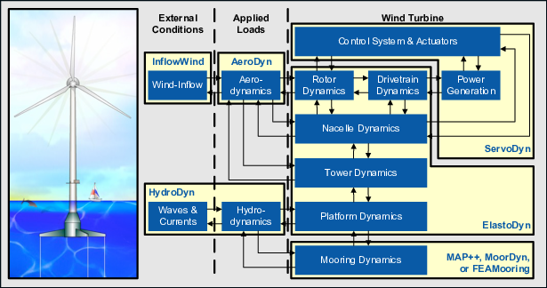
Fig. 4.12 OpenFAST schematic
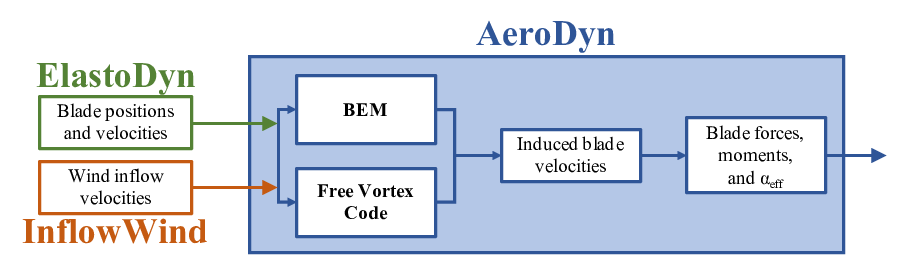
Fig. 4.13 OLAF and BEM integration with AeroDyn
Incorporating the OLAF module within OpenFAST allows for the modeling of highly flexible turbines along with the aero-hydro-servo-elastic response capabilities of OpenFAST. The OLAF module follows the requirements of the OpenFAST modularization framework ([olaf-Jon13, olaf-SJJ15]).
The OLAF module uses a lifting-line representation of the blades, which is characterized by a distribution of bound circulation. The spatial and time variation of the bound circulation results in free vorticity being emitted in the wake. OLAF solves for the turbine wake in a time-accurate manner, which allows the vortices to convect, stretch, and diffuse. The OLAF model is based on a Lagrangian approach, in which the turbine wake is discretized into Lagrangian markers. There are many methods of representing the wake with Lagrangian markers ([olaf-Bra17]). In this work, a hybrid lattice/filament method is used, as depicted in Figure Fig. 4.14.
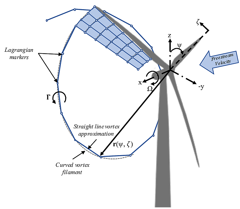
Fig. 4.14 Evolution of near-wake lattice, blade-tip vortex, and Lagrangian markers
Here, the position of the Lagrangian markers is defined in terms of wake age, \(\zeta\), and azimuthal position, \(\psi\). A lattice method is used in the near wake of the blade. The near wake spans over a user-specified angle or distance for nonrotating cases. Though past research has indicated that a near-wake region of \(30^\circ\) is sufficient ([olaf-ALR02, olaf-Lei06]), it has been shown that a larger near wake is required for high thrust and other challenging conditions. After the near wake region, the wake is assumed to instantaneously roll up into a tip vortex and a root vortex, which are assumed to be the most dominant features for the remainder of the wake ([olaf-LBB02]). Each Lagrangian marker is connected to adjacent markers by straight-line vortex filaments, approximated to second-order accuracy ([olaf-GL02]). The wake is discretized based on the spanwise location of the blade sections and a specified time step (\(dt\)), which may be different from the time step of AeroDyn. After an optional initialization period, the wake is allowed to move and distort, thus changing the wake structure as the markers are convected downstream. To limit computational expense, the root and tip vortices are truncated after a specified distance (taken as a number of panels nNWPanels) downstream from the turbine. The wake truncation violates Helmholtz’s first law and hence introduces an erroneous boundary condition. To alleviate this, the wake is “frozen” in a buffer zone between a specified buffer distance, nFWPanelsFree, and nFWPanels. In this buffer zone, the markers convect at the average ambient velocity. In this way, truncation error is minimized~([olaf-LBB02]). The buffer zone is typically chosen as the convected distance over one rotor revolution.
As part of OpenFAST, induced velocities at the lifting line/blade are transferred to AeroDyn and used to compute the effective blade angle of attack at each blade section, which is then used to compute the aerodynamic forces on the blades. The OLAF method returns the same information as the BEM method, but allows for more accurate calculations in areas where BEM assumptions are violated, such as those discussed above. As the OLAF method is more computationally expensive than BEM, both methods remain available in OpenFAST, and the user may specify in the AeroDyn input file which method is used.
The OLAF input file defines the wake convection and circulation solution methods; wake size and length options; Lagrangian marker regularization (viscous core) method; and other simulation and output parameters. The extents of the near and far wakes are specified by a nondimensional length in terms of rotor diameter. Different regularization functions for the vortex elements are available. Additionally, different methods to compute the regularization parameters of the bound and wake vorticity may be selected. In particular, viscous diffusion may be accounted for by dynamically changing the regularization parameter. Wake visualization output options are also available.
This document is organized as follows. Section 4.4.3.1 covers downloading, compiling, and running OLAF. Section 4.4.4 describes the OLAF input file and modifications to the AeroDyn input file. Section 4.4.5 details the OLAF output file. Section 4.4.6 provides an overview of the OLAF theory, including the free vortex wake method as well as integration into the AeroDyn module. Example input files and a list of output channels are detailed in Appendices A, B, and C.